Table of Contents
Advertisement
Advertisement
Table of Contents

Related Manuals for Vertiv HPL


Summary of Contents for Vertiv HPL
- Page 1 Vertiv™ HPL Lithium-Ion Energy Storage System Operation Guide...
- Page 2 The products covered by this instruction manual are manufactured and/or sold by Vertiv. This document is the property of Vertiv and contains confidential and proprietary information owned by Vertiv. Any copying, use or disclosure of it without the written permission of Vertiv is strictly prohibited.
-
Page 3: Table Of Contents
4.2.4 Word Count 4.2.5 Example 4.3 Modbus Register Mapping 4.3.1 Common Data 4.3.2 System Data Appendices Appendix A: Technical Specifications Appendix B: Warnings and Faults Appendix C: Cabinet Terminal Block Vertiv | Vertiv™ HPL Lithium-Ion Energy Storage System Operation Guide |... - Page 4 Vertiv | Vertiv™ HPL Lithium-Ion Energy Storage System Operation Guide |...
-
Page 5: Important Safety Instructions
IMPORTANT SAFETY INSTRUCTIONS Read and follow these instructions! The following precautions are intended to ensure your safety and prevent property damage. Before installing this product, be sure to read all safety instructions in this document for proper installation. Failure to comply with the instructions with this symbol may result in a serious accident, causing death or a severe injury. WARNING! Failure to comply with the instructions with this symbol may result in a serious accident, causing severe injury or death. - Page 6 Transport legally and follow the manufacturer's instructions for disposal. Please recycle your lithium-ion battery - do not discard. GROUND This symbol indicates a ground point. Ground wires must be connected to a point with this symbol Vertiv™ | Vertiv™ HPL Lithium-Ion Energy Storage System Operation Guide...
-
Page 7: Overview
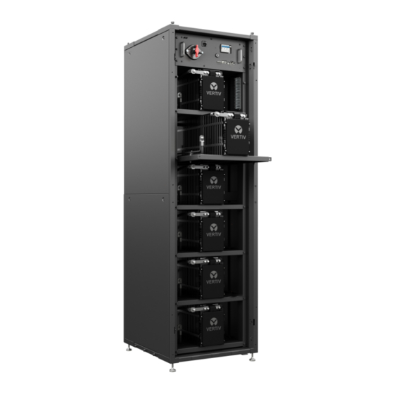
1 OVERVIEW The Vertiv™ HPL Lithium-Ion Energy Storage System is a high-power DC battery system for use with Vertiv Uninterruptible Power Supply (UPS) units, including the Liebert® EXL S1, Liebert® NXL, Liebert® EXM 480V, Liebert® NX and Liebert® Series 610 products. This guide provides information necessary to operate the Vertiv HPL correctly. - Page 8 Power Chassis Assembly (PCA) Module 4 Cabinet Terminal Block (CTB) Refer to Vertiv™ submittal drawings for signal wiring requirements and interconnection assignments, based on UPS type. The following table lists which drawings to refer to for each UPS. Table 1.2 UPS Submittal Drawings UPS TYPE...
-
Page 9: Equipment Handling
Warning!: Do not operate when the CTL PWR BREAKER is closed, except as specifically directed tag-out feature when logged in to the service console. Service power input jack (120VAC For use by Vertiv™ service personnel only. Provides control power for servicing the unit when battery 50/60Hz) power is unavailable. RUN/SERVICE key switch For use by Vertiv service personnel under guidance from tech support only. -
Page 10: Local Interface
NOTICE! Risk of improper equipment operation. Can cause serious damage to the Vertiv HPL. The S1 maintenance disconnect is a static isolation and lockout device only and should not be operated while the Vertiv HPL is online. Doing so will damage the equipment. To open the disconnect you must follow the procedure below. -
Page 11: Liquid Crystal Display
ITEM DESCRIPTION ENABLE button STOP RESET button Along with the Modbus/TCP interface, the local interface is the primary means of interacting with the Vertiv HPL. For more information about the Modbus interface, see Modbus Communication on page 9. 2.3.1 Liquid Crystal Display Figure 1.4 LCD Layout... -
Page 12: Enable And Stop Buttons
2.3.2 Enable and Stop buttons The ENABLE button is at the right of the local interface. This button enables the Vertiv™ HPL Lithium-Ion Energy Storage System to join the DC bus when conditions are right. Until that time, the rack will be in WAITING mode, as evidenced by the flashing LED (color dependent on the rack status) around the ENABLE button. -
Page 13: Operation
NOTICE! Risk of improper equipment operation. Can cause serious damage to the Vertiv HPL. The S1 maintenance disconnect is a static isolation and lockout device only and should not be operated while the Vertiv HPL is online. Doing so will damage the equipment. -
Page 14: Leds
3.3 LEDs Each push button on the local interface has corresponding LED indicators to provide feedback on the status of the Vertiv™ HPL Lithium-Ion Energy Storage System. LED Descriptions on page 8 describes the rack LEDs. WARNING! Both LEDs being solid red indicates the BMS software is not running. When the BMS software is not running, the rack is disconnected from the DC bus. -
Page 15: Modbus Communication
The function code field tells the addressed slaves what function to perform. Function codes are designed to invoke a specific action by the slave device. The function code ranges from 1 to 127. The Vertiv™ HPL Modbus server supports the following Modbus function codes, yet the initial release will only include Input Registers for read-only. -
Page 16: Reference Number
SCALE UNITS NOTES REGISTER Common Data Major – upper 8 bits BMS Protocol 30001 0 (0x0h) Major/Minor Minor – lower 8 bits Enclosure Position 30002 1 (0x1h) Range: 1 - 32 Vertiv™ | Vertiv™ HPL Lithium-Ion Energy Storage System Operation Guide... -
Page 17: System Data
4.3.2 System Data Table 3.2 System Data Descriptions DATA DESCRIPTION INPUT REGISTER REFERENCE # # OF REG SCALE UNITS NOTES BMS Enclosure Count 30101 100 (0x64h) Range: 1 - 32 System Warning LED Sync System Status Flags 30201 200 (0xC8h) Unable To Carry Load Faulted Racks Mains Fail... - Page 18 Range: -3000 - 3000 Temperature Enclosure 1 Battery 31026 1025 (0x401h) °C Range: -3000 - 3000 Temperature Enclosure 1 Battery Cell 31027 1026 (0x402h) 1000 Range: 0 – 6000 Voltage Min Vertiv™ | Vertiv™ HPL Lithium-Ion Energy Storage System Operation Guide...
- Page 19 Table 3.3 Enclosure Data Descriptions (continued) DATA INPUT REFERENCE# SCALE UNITS NOTES DESCRIPTION REGISTER Enclosure 1 Battery Cell 31028 1027 (0x403h) 1000 Range: 0 – 6000 Voltage Max Enclosure 1 Temperature 5000 35001 Range: 1 – 10 Values per (0x1388h) Battery Enclosure 1 5001...
- Page 20 35052 °C Range: -3000 - 3000 (0x13BBh) Enclosure 2 5052 Battery Temp 35053 °C Range: -3000 - 3000 (0x13BCh) Enclosure 2 5062 Battery Temp 35063 °C Range: -3000 - 3000 (0x13C6h) Vertiv™ | Vertiv™ HPL Lithium-Ion Energy Storage System Operation Guide...
- Page 21 Table 3.3 Enclosure Data Descriptions (continued) DATA INPUT REFERENCE# SCALE UNITS NOTES DESCRIPTION REGISTER Enclosure 2 6150 Cell Voltages 36151 Range: 1 - 32 (0x1806h) Per Battery Enclosure 2 6151 36152 1000 Range: 0 - 6000 Cell Voltage 1 (0x1807h) Enclosure 2 6152 36153...
- Page 22 Range: 0 - 6000 Cell Voltage 2 (0x189Eh) Enclosure 3 6432 Cell Voltage 36433 Range: 0 - 6000 (0x1920h) Enclosure 4 Enclosure 4 31301 1300 (0x514h) Range: 1 - 32 Battery Count Vertiv™ | Vertiv™ HPL Lithium-Ion Energy Storage System Operation Guide...
- Page 23 Table 3.3 Enclosure Data Descriptions (continued) DATA INPUT REFERENCE# SCALE UNITS NOTES DESCRIPTION REGISTER Enclosure 4 31302 1301 (0x515h) Enabled Enclosure 4 31303 1302 (0x516h) See Enclosure 1 Status 1. Status 1 Enclosure 4 31305 1304 (0x518h) See Enclosure 1 Status 2. Status 2 Enclosure 4 31307...
- Page 24 1406 (0x57Eh) See Enclosure 1 Status 3. Status 3 Enclosure 5 31418 1417 (0x589h) Range: 0 - 1000 Target SOC Enclosure 5 Percent 31419 1418 (0x58Ah) Range: 0 - 1000 Charged Vertiv™ | Vertiv™ HPL Lithium-Ion Energy Storage System Operation Guide...
- Page 25 Table 3.3 Enclosure Data Descriptions (continued) DATA INPUT REFERENCE# SCALE UNITS NOTES DESCRIPTION REGISTER Enclosure 5 Runtime 31420 1419 (0x58Bh) Range: 0 - 1800 Remaining Enclosure 5 DC 31421 1420 (0x58Ch) Range: 380 - 600 Bus Voltage Enclosure 5 DC 31422 1421 (0x58Dh) Range: -32768 - 32768...
- Page 26 31523 1522 (0x5F2h) Range: 0 - 65535 Voltage Enclosure 6 Battery 31524 1523 (0x5F3h) Range: -32768 - 32768 Current Enclosure 6 Battery 31525 1524 (0x5F4h) °C Range: -3000 - 3000 Temperature Vertiv™ | Vertiv™ HPL Lithium-Ion Energy Storage System Operation Guide...
- Page 27 Table 3.3 Enclosure Data Descriptions (continued) DATA INPUT REFERENCE# SCALE UNITS NOTES DESCRIPTION REGISTER Enclosure 6 Battery 31526 1525 (0x5F5h) °C Range: -3000 - 3000 Temperature Enclosure 6 Battery Cell 31527 1526 (0x5F6h) 1000 Range: 0 – 6000 Voltage Min Enclosure 6 Battery Cell 31528...
- Page 28 Range: 0 – 6000 Voltage Max Enclosure 7 Temperature 5300 35301 Range: 1 - 10 Values per (0x14B4h) Battery Enclosure 7 5301 Battery Temp 35302 °C Range: -3000 - 3000 (0x14B5h) Vertiv™ | Vertiv™ HPL Lithium-Ion Energy Storage System Operation Guide...
- Page 29 Table 3.3 Enclosure Data Descriptions (continued) DATA INPUT REFERENCE# SCALE UNITS NOTES DESCRIPTION REGISTER Enclosure 7 5302 Battery Temp 35303 °C Range: -3000 - 3000 (0x14B6h) Enclosure 7 5312 Battery Temp 35313 °C Range: -3000 - 3000 (0x14C0h) Enclosure 7 6900 Cell Voltages 36901...
- Page 30 Range: -3000 - 3000 (0x14F2h) Enclosure 8 7050 Cell Voltages 37051 Range: 1 - 32 (0x1B8Ah) Per Battery Enclosure 8 7051 37052 1000 Range: 0 - 6000 Cell Voltage 1 (0x1B8Bh) Vertiv™ | Vertiv™ HPL Lithium-Ion Energy Storage System Operation Guide...
- Page 31 Table 3.3 Enclosure Data Descriptions (continued) DATA INPUT REFERENCE# SCALE UNITS NOTES DESCRIPTION REGISTER Enclosure 8 7052 37053 1000 Range: 0 - 6000 Cell Voltage 2 (0x1B8Ch) Enclosure 8 7182 Cell Voltage 37183 Range: 0 - 6000 (0x1C0Eh) 4 Modbus Communication...
- Page 32 This page intentionally left blank Vertiv™ | Vertiv™ HPL Lithium-Ion Energy Storage System Operation Guide...
-
Page 33: Appendices
NOTES 600mm x 725mm x 2010mm (23.6" Dimensions Without optional conduit box. x 28.5" x 79.1") Shipped assembled with exception of five inter-tier jumpers connected by Vertiv service Weight Appx 500kg (1102 lb.) personnel at commissioning time. Cell Type Lithium-Ion NMC Pouch Cell... - Page 34 Derated run times to avoid overtemperature until recovery complete. Balancing Circuitry Resistive Cell groups are balanced as required for optimal performance. Compliance UL1973, ISTA, UNDOT 38.3, FCC 47 CFR 15B – Class B. Vertiv™ | Vertiv™ HPL Lithium-Ion Energy Storage System Operation Guide...
-
Page 35: Appendix B: Warnings And Faults
Appendix B: Warnings and Faults Table B.1 Warning and Fault Descriptions FAULT/GRACE DISPLAY MESSAGE WARNING FAULT FAULT RESET COMMENT PERIOD Welded C1. Current flowing when C1 is Check Main Contactor commanded Open. Door Open 60 sec. Closed Warning, Fault after 60 seconds. Service Mode Service Key in SERVICE position. - Page 36 MBB Volt/Temp Delta 15 sec. temperature. Or MBB voltage or temperature deviation failure. any battery module group voltage difference more than 1.5V from the MBB average. UPS Not Talking UPS on CAN1 is not talking. Vertiv™ | Vertiv™ HPL Lithium-Ion Energy Storage System Operation Guide...
- Page 37 Table B.1 Warning and Fault Descriptions (continued) FAULT/GRACE DISPLAY MESSAGE WARNING FAULT FAULT RESET COMMENT PERIOD Internal IO board has a regulated power supply IOB Reg PS Failure failure. A reversed polarity has been detected on the Polarity Fault DC bus. Peer enclosure disconnect discrete has been Disconnect Requested asserted.
-
Page 38: Appendix C: Cabinet Terminal Block
UPS is ready when tied to CTB-10. DISCONNECT_REQUEST_ CTB-18 Input Coordinated disconnect has been requested when shorted to CTB-10. CTB-19 CAN1_HI CAN_HI signal for inter-rack communications. CTB-20 CAN1_LO CAN_LO signal for inter-rack communications. Vertiv™ | Vertiv™ HPL Lithium-Ion Energy Storage System Operation Guide... - Page 39 Vertiv™ | Vertiv™ HPL Lithium-Ion Energy Storage System Operation Guide...
- Page 40 Vertiv.com | Vertiv Headquarters, 1050 Dearborn Drive, Columbus, OH, 43085, USA © 2019-2020 Vertiv Group Corp. All rights reserved. Vertiv™ and the Vertiv logo are trademarks or registered trademarks of Vertiv Group Corp. All other names and logos referred to are trade names, trademarks or registered trademarks of their respective owners.
Need help?
Do you have a question about the HPL and is the answer not in the manual?
Questions and answers