
Related Manuals for Johnson Controls Tyco Kantech KT-MOD-IO16


Summary of Contents for Johnson Controls Tyco Kantech KT-MOD-IO16
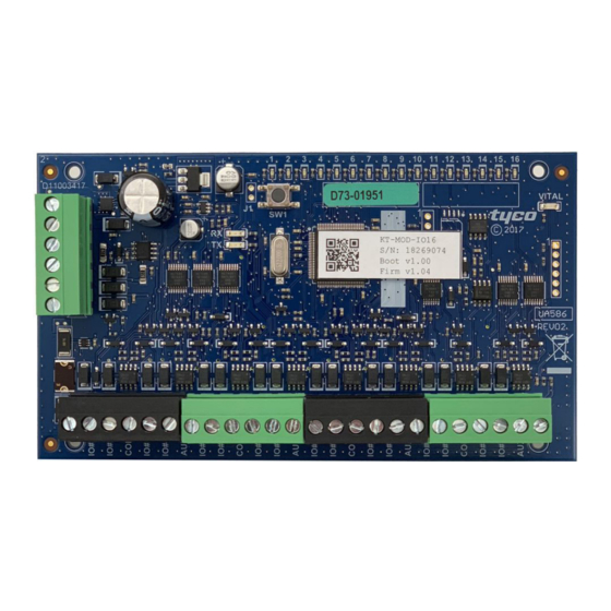
- Page 1 KT-MOD-IO16 RS-485 Input/Output Module Installation Guide DN2238-1908 D29010415R002 www.kantech.com...
-
Page 2: Table Of Contents
Contents TYCO INTERNATIONAL LTD END-USER LICENSE AGREEMENT 3 Copyright information Safety instructions Technical support Box contents Technical specifications Basic wiring diagram Vital LED indicator chart SPI modules Resetting the KT-MOD-IO16 Input and output terminals Mounting the KT-MOD-IO16 Installing and wiring the KT-MOD-IO16 Compliance specifications KT-MOD-IO16 RS-485 Input/Output Module Installation Guide... -
Page 3: Tyco International Ltd End-User License Agreement
TYCO INTERNATIONAL LTD END-USER LICENSE AGREEMENT For KANTECH software provided with or without products or components IMPORTANT: READ CAREFULLY KANTECH software purchased with or without products and components is copyrighted and is purchased under the following license terms: • This End-User License Agreement (“EULA”) is a legal agreement between You (the company, individual or entity who acquired the Software and any related Hardware) and KANTECH, the manufacturer of the integrated security systems and the developer of the software and any related products... - Page 4 c - Backup Copy - You may make back-up copies of the SOFTWARE PRODUCT, but You may only have one copy per license installed at any given time. You may use the back-up copy solely for archival purposes. Except as expressly provided in this EULA, You may not otherwise make copies of the SOFTWARE PRODUCT, including the printed materials accompanying the SOFTWARE.
- Page 5 other intellectual property laws and treaties. This EULA grants You no rights to use such content. All rights not expressly granted under this EULA are reserved by KANTECH and its suppliers. 4 - EXPORT RESTRICTIONS You agree that You will not export or re-export the SOFTWARE PRODUCT to any country, person, or entity subject to US export restrictions.
- Page 6 WARRANTIES. KANTECH NEITHER ASSUMES NOR AUTHORIZES ANY OTHER PERSON PURPORTING TO ACT ON ITS BEHALF TO MODIFY OR TO CHANGE THIS WARRANTY, NOR TO ASSUME FOR IT ANY OTHER WARRANTY OR LIABILITY CONCERNING THIS SOFTWARE PRODUCT. e - EXCLUSIVE REMEDY AND LIMITATION OF WARRANTY UNDER NO CIRCUMSTANCES SHALL KANTECH BE LIABLE FOR ANY SPECIAL, INCIDENTAL, CONSEQUENTIAL OR INDIRECT DAMAGES BASED UPON BREACH OF WARRANTY, BREACH OF...
- Page 7 j - Termination - Without prejudice to any other rights, KANTECH may terminate this EULA if You fail to comply with the terms and conditions of this EULA. In such event, You must destroy all copies of the SOFTWARE PRODUCT and all of its component parts. k - Trademarks - This EULA does not grant You any rights in connection with any trademarks or service marks of KANTECH or its suppliers.
-
Page 8: Copyright Information
Copyright information © 2019 Johnson Controls. All rights reserved. JOHNSON CONTROLS, TYCO and KANTECH are trademarks and/or registered trademarks. Unauthorized use is strictly prohibted. Safety instructions Important: Never install the equipment during a lightning storm. This equipment, KT-MOD-IO16 RS-485 Input/Output Module, shall be installed and used within an environment that provides the pollution degree max 2 and over voltages category II NON HAZARDOUS LOCATIONS, INDOOR only. - Page 9 Reducing the clearance between SELV (Safety Extra Low Voltage) circuits and NON-POWER Limited Circuits (Battery wires) Route the battery wires away from the rest of the SELV circuit 6. It is the end-user and/or installer's responsibility to ensure that the disposal of the used batteries is made according to the waste recovery and recycling regulations applicable to the intended market.
-
Page 10: Technical Support
Technical support For technical support, email access-support@jci.com during business hours or go to: http://www.kantech.com/Support/Contact_Technical_Support_ Advanced.aspx The following table lists the technical support phone numbers and opening hours. Table 1: Technical support contact details USA and Canada GMT - 05:00 08:00 to 20:00 North America Toll Free +1 888 222 1560... - Page 11 Australia Direct +02 9684 3980 EMEA GMT + 01:00 08:00 TO 18:00 Toll free +800 CALL TYCO +800 2255 8926 Direct +31 475 352 722 United Kingdom Direct +44 330 777 1300 Israel Direct +972 772 201 350 Spain Direct +900 99 31 61 France Direct...
-
Page 12: Box Contents
Box contents • One KT-MOD-IO16 RS-485 Input/Output module. • One installation manual. • One accessory kit containing four plastic standoffs and thirty-two 5.6K EOL resistors. Technical specifications The following table lists the technical specifications of the KT-MOD-IO16. Table 2: Technical specifications Dimensions (H x W x D) 31.5 x 146 x 82.6 mm (1.25 x 5.75 x 3.25 in.) Weight 118 g (1/4 lb) - Page 13 Tamper NC input (NEOL) Mounting Mount the PCB in a compatible cabinet. The KT- MOD-CAB is recommended. Communication RS-485 AES 128-bit RS-485 cabling 2 twisted pairs, unshielded, up to 1200 m (4000 ft). For more information, see Installing and wiring the KT-MOD-IO16.
-
Page 14: Basic Wiring Diagram
Basic wiring diagram The following figure illustrates the basic wiring configuration of the KT-MOD- IO16. Figure 1: Basic wiring diagram KT-MOD-IO16 RS-485 Input/Output Module Installation Guide... - Page 15 The following table describes the wiring, condition, and state of each input configuration. Table 3: Contact input configuration Input Contact Wiring Condition State configuration type Dry contact See Figure A short is detected. Secure without an An open condition is detected. Alarm EOL resistor See Figure An open condition is detected.
- Page 16 The following table provides illustrations of the wiring for each contact input configuration. Table 4: Contact input wiring Figure 2 Figure 3 NC Dry contact NO Dry contact Figure 4 Figure 5 NC Dry contact with EOL resistor NO Dry contact with EOL resistor Figure 6 NC Dry contacts with double EOL resistors KT-MOD-IO16 RS-485 Input/Output Module Installation Guide...
-
Page 17: Vital Led Indicator Chart
Vital LED indicator chart The following table describes the LED sequences of the KT-MOD-IO16. Table 5: Vital LED indicator chart Device state LED sequence Description Firmware upgrade Quick pulses. 5 pulses every second at 50% duty cycle. Factory default Continuous long pulses. -
Page 18: Spi Modules
SPI modules Figure 7: SPI modules wiring diagram KT-MOD-IO16 RS-485 Input/Output Module Installation Guide... - Page 19 SPI information Each KT-MOD-IO16 can support 8 SPI relay modules, up to a total of 64 relays (SPI) for each module. These can be with or without elevator control. You can have a total of 32 SPI relay modules. Power limitations from KT controllers The specifications for KT-MOD-REL8 modules or multi-io modules apply up to a maximum of 32 modules.
-
Page 20: Resetting The Kt-Mod-Io16
Resetting the KT-MOD-IO16 You can execute a soft reset or a factory default reset on the KT-MOD-IO16 by using the SW1 button on the board. Executing a soft reset To execute a normal soft reset, press the SW1 button for more than 100 ms (debounce) but for less than 3 seconds. -
Page 21: Mounting The Kt-Mod-Io16
Mounting the KT-MOD-IO16 Mount the KT-MOD-IO16 in a compatible KT-MOD-CAB or KT-400-CAB cabinet. Alternatively, mount the KT-MOD-IO16 in a dry and secure location. To mount the KT-MOD-IO16 in a compatible cabinet, complete the following steps: 1. Insert the four plastic standoffs through the mounting holes of the KT-MOD- IO16. - Page 22 External power to 12 VDC input • Recommended cable type: The length of the cable and the amount of power supplied by the KT-MOD-IO16 determine the size of the wire you should use. Use the appropriate wiring size for your application. In some cases, you can use one or two wires of a CAT5 cable for the negative side and one or two wires of a CAT5 cable for the positive side.
- Page 23 • Recommended cable type: The length of the cable and the amount of power supplied to the outputs, if any, determine the size of the wire you should use. Use the appropriate wiring size for your application. In some cases, you can use one or two wires of a CAT5 cable. In other cases, you use a 22 AWG cable or bigger.
-
Page 24: Compliance Specifications
Compliance specifications United States This equipment has been tested and found to comply with the limits for a Class B digital device, pursuant to Part 15 of the FCC rules. These limits are designed to provide reasonable protection against harmful interference in a residential installation. - Page 26 © 2019 Johnson Controls. All rights reserved.
Need help?
Do you have a question about the Tyco Kantech KT-MOD-IO16 and is the answer not in the manual?
Questions and answers