Table of Contents
Advertisement
Advertisement
Table of Contents

Related Manuals for Growatt GBLI Series


Summary of Contents for Growatt GBLI Series
- Page 1 6.5kWh Residential Energy Storage Battery Manual Version: 1.1 Date: 2019-08-07...
- Page 2 This document describes the application scenarios, installation, electrical connection, commission and troubleshooting of 6.5kWh Residential Energy Storage Battery (hereinafter simply put as battery). Before installing and operating battery, please ensure that you are familiar with product features, functions, and safety precautions as provided in this document. Warning and caution messages are listed in the document to remind users, installers and maintainer of safe operation.
-
Page 3: Table Of Contents
Table of Contents 1 Safety ............................. 3 1.1 Warning Label ........................3 1.2 Precautions .......................... 4 1.3 Responses to Emergencies ....................4 1.4 Storage safety ........................5 1.5 Transportation Safety ......................5 2. Introduction to Product ......................7 2.1 Intended Purpose ......................... 7 2.2 Function .......................... -
Page 4: Safety
Safety 1 Safety 1.1 Warning Label Do not dispose battery in household trash. Recyclable. Certification in European Union area. Risk of electric shock. Explosive gas. Battery may leak corrosive electrolyte. Battery is heavy enough to cause severe injury. Keep battery away from children. Do not reverse polarities. -
Page 5: Precautions
Safety Nameplate Label 1.2 Precautions Risks of electrolyte leakage Do not subject battery to strong impact. Do not crush or puncture battery. Do not open or mutilate batteries. Released electrolyte is harmful to the skin and eyes. Risks of fire ... -
Page 6: Storage Safety
Safety Immediately seek for medical intervention after taking emergency measures. Fire Battery may catch fire when heated above 150℃. Please implement the following actions: Extinguish fire before the battery catches fire. ABC or carbon dioxide extinguisher is recommended. If the fire is too strong to put out, move battery to a safe place before it catches fire. - Page 7 Safety SN/T 0370.2-2009 (Part 2: Performance Test of the Rules for the Inspection of packaging for Exporting Dangerous Goods). The battery is classified as class 9 dangerous goods, and is subject to land and water transportation. It is mandatory to report to the airline company and obtain approval before air transport.
-
Page 8: Introduction To Product
Introduction to Product 2. Introduction to Product 2.1 Intended Purpose The battery is a 6.5kWh LiFePO4 pack. It has a 48V battery module as the main power supply unit which composed of 32 64Ah cells in two parallel and sixteen serial connect (2P16S). -
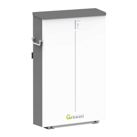
Page 9: Appearance
Introduction to Product Monitoring: detect the voltage and temperature of cell, the voltage and current of battery. SOC estimate: indicate the precise volume of remaining electricity. Alarm: alarm when overvoltage, under voltage, overcurrent, over temperature or under temperature occurs. -
Page 10: Technical Parameters
Introduction to Product 2.4 Technical Parameters Item Specification Nominal capacity/energy 128Ah/6.5kWh Rated/usable capacity/energy 118Ah/6.0kWh Typical voltage 51.2 V Operating voltage 48V ~57.6V Standard charging current (25℃) Max. discharging current (25℃,3s) Continual Max. discharging current (25℃)——85A Rated discharging power 3.3kW Max. discharging power 4.4kW Peak discharging power 5kW/3S... -
Page 11: Installation
Installation 3 Installation 3.1 Basic Installation Requirements Battery can be installed indoors or outdoors. Ensure the following conditions are satisfied: ≤Ө≤5 A deviation of -5 is allowed for both installation against wall and floor. Additionally, the distance between the bottom part of battery and floor should not exceed 500mm. -
Page 12: Installation Required Tools
Installation Keep the dirt or dust at a minimal level; Do not install battery in a place where flood frequently occurs; Do not install battery in highly humid area such as bathroom; Ensure direct contact between battery shell and ambient air. Do not cover or shield battery to avoid poor cooling. -
Page 13: Wall Mounted Installation
Installation Standard Accessories Single battery Parallel-connected batteries 1 PCS 2PCS Battery Positive terminal 1PCS (Min. 3 AWG) Positive terminal 2PCS (Min. 3 AWG) Terminal Negative terminal 1PCS (Min. 3 AWG) Negative terminal 2PCS (Min. 3 AWG) Network terminal 1PCS(Min. 26 AWG) Network terminal 3PCS(Min. - Page 14 Installation Step 2 Fix bracket to wall. Choose alloy drill bit with a diameter of 12mm and install it to a drill. Drill in the four spots that have been located in step 1 and have at least 60mm drilling depth. Clean the soil and drive expansion tube into the hole.
-
Page 15: Floor Standing Installation
Installation 3.3.2 Floor Standing Installation Step 1 Confirm installation spot. Place battery in the to-be installed area. Rotate the left latch leftward and the right latch rightward until they are perpendicular to the battery. Keep the distance between wall and battery as shown (300mm, 300mm). Leave a minimum clearance of 133mm before the front surface of battery. -
Page 16: Electrical Connection
Electrical Connection 4 Electrical Connection 4.1 Preparation Item Definition RS485B RS485A GND2 CANH COM1/ COM2 CAHL GND2 WAKE- 4.2 Electrical Connection Procedures WAKE+ Step 1 Connect grounding cable. It is recommended to fasten grounding terminal and grounding cable with M6 screw. Step 2 Make power cables. - Page 17 Electrical Connection Step 3 Make network cables. 1. Strip cable sheaths for 15± 0.5mm first. 2. Network cable adopts standard 8-core Insert sealing and sealing nut along the cable. Reserve two wires, cut the other cable. six wires. Make CAN network cable: insert the two remaining wires into pin 4 and pin 5 of RJ45 plug.
-
Page 18: Installation Steps Under Parallel Connection
Installation Steps under Parallel Connection 5 Installation Steps under Parallel Connection Step 1 Install battery. Power on two batteries in condition of no load, measure their voltages with a multi-meter and confirm the voltage difference not more than 1V. After that, power off two batteries and install them according to the procedures specified in Section 3.3. - Page 19 Installation Steps under Parallel Connection RS485 network cable only applies to the communication between two batteries, and CAN network cable only applies to the communication between battery and PCS. Ensure two batteries in parallel connection are from the same batch, same model and same manufacturer.
-
Page 20: Power On/Off Battery
Power on/off Battery 6 Power on/off Battery There are many technical contents involved in the electrification process, and technicians must go through technical training and obtain certificates in compliance with local laws and regulations. Please stand on dry insulating objects and do not wear metal objects such as watches, rings and necklaces during operation. -
Page 21: Power On Battery
Power on/off Battery 6.2 Power on Battery Power on single battery by pressing POWER button Procedures Acceptation criteria Close the breaker that is connected with positive and negative power Breaker in ON position. cables. 1. If both RUN and SOC lights turn on Press POWER button for two seconds normal, battery powers on successfully;... -
Page 22: Power Off Battery
Power on/off Battery mains supply input. 1. If RUN lights and SOC lights on both batteries indicate normal, and RUN lights on both batteries flicker for five times, two batteries power on successfully and PCS voltage signal activates battery. communication between batteries works; 2. -
Page 23: Maintenance
Maintenance 7 Maintenance 7.1 Preparation Battery replacement should be conducted by professionals. Prepare tools like safety gloves, cross head driver and socket wrench. Ensure undamaged appearance and complete accessories of new battery. Do not change battery in rainy or stormy days. ... -
Page 24: Troubleshooting
Maintenance 2. Choose “ ” for device type and “Extend” for CANalyst-II Frame Type, set “500Kbps” baud rate. Keep other default parameters. Click “OK”. 3. Choose target upgrade file. 4. Click “Start to Upgrade”. 5. Upgrade succeeds when progress bar reaches 100%. 7.4 Troubleshooting Error Indication Error description... - Page 25 Maintenance Protection against level three Cell surface temperature low temperature charge.. There is no safety threat and below battery temperature Protection against level three user should stop using battery. low limit. low temperature discharge. Protection against level three There is safety risk and user Cell surface temperature high temperature charge.
- Page 26 Maintenance confirmed well connected, user should contact installer to repair battery. There is safety risk and user Current limitation failure, should stop using battery. Current limit failure. ALM light maintains on. User should contact installer to repair battery. T: +86 0755 2747 1942 E: service@ginverter.com W: www.ginverter.com Address: No.
Need help?
Do you have a question about the GBLI Series and is the answer not in the manual?
Questions and answers