Advertisement
Quick Links
The Dakota Digital SGI-5 E is designed to recalibrate a speedometer signal or correct
sinewave(AC)/squarewave('oc') signal incompatibilities. Here are some typical applications:
1. Recalibrate a high speed (32,000ppm – 250,000ppm) signal for an OEM speedometer. Do not
use this unit to adjust a signal going to an anti-lock braking system.
2. Recalibrate a low speed (32,000ppm – 4,000ppm) signal for an OEM or aftermarket speedometer
or fuel injection computer.
3. Convert a high-speed signal found on newer GM transmissions down to a low speed signal to run
a speedometer, cruise control, or fuel injection computer.
4. Convert an 8000ppm signal from an aftermarket signal generator to a 4000ppm or 2000ppm to
run an OEM cruise control or fuel injection computer.
5. Convert a 16000ppm signal from a VDO Hall Effect signal generator to an 8000ppm, 4000ppm, or
2000ppm to run a cruise control or fuel injection computer.
6. Convert a 4000ppm signal from an OEM transmission speed sensor or ECM output to an
8000ppm signal for an aftermarket speedometer.
7. Convert an 8000ppm or 16000 ppm signal up to a high-speed 128,000ppm signal for a newer fuel
injection computer.
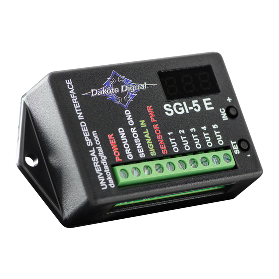
SGI-5 E wiring connections:
Please Note: This is a technically advanced product and if not installed correctly may cause
incorrect vehicle operation and/or damage to vehicle components.
UNIVERSAL SIGNAL INTERFACE UNIT
12V Accessory Power
GROUND
Sensor ground (if needed)
Speed input signal
Sensor 5V power (if needed)
SGI-5 E
SGI-5 E
+
ppm values listed
below are only valid
after calibration is
-
complete
calibrated 'oc' output signal
calibrated 'AC' output signal
1
2000 ppm 'oc' output
4000 ppm 'oc' output
8000 ppm 'AC' output
MAN# 650528 rev. B
Advertisement

Related Manuals for Dakota Digital SGI-5 E


Summary of Contents for Dakota Digital SGI-5 E
- Page 1 SGI-5 E UNIVERSAL SIGNAL INTERFACE UNIT The Dakota Digital SGI-5 E is designed to recalibrate a speedometer signal or correct sinewave(AC)/squarewave(‘oc’) signal incompatibilities. Here are some typical applications: 1. Recalibrate a high speed (32,000ppm – 250,000ppm) signal for an OEM speedometer. Do not use this unit to adjust a signal going to an anti-lock braking system.
-
Page 2: Advanced Setup
If, without the interface, your speedometer reads much too slow, then you will most likely need to use application 7. Here is a general overview of the SGI-5 E’s control functions. Each of the different applications below will be described in detail starting on page 4 in this manual. - Page 3 Calibration Adjust while driving: To increase the speedometer reading, press and hold the + push button switch. To decrease the speedometer reading, press and hold the - push button switch. The calibration will only change when the vehicle is in motion and a speed signal is present. Preset or adjust while parked: The calibration value can be set from 0.250 –...
- Page 4 3. Actual speed ------------------------------- x current Cal ratio new Cal ratio speedometer reading SGI-5 E 12V Accessory Power GROUND Sensor ground (if needed) calibrated 'oc' output signal Speed input signal...
- Page 5 You must first determine which wire is the signal. The signal wire will need to be cut so the SGI-5 E can recalibrate it. The sensor side of the wire will go to the SIGNAL IN terminal. The speedometer or computer side will go to the OUT1 terminal. If the speedometer does not operate correctly after installation of the SGI-5 E you may need to switch to OUT2 instead of OUT1.
- Page 6 3. Actual speed ------------------------------- x current Cal ratio new Cal ratio speedometer reading SGI-5 E ppm values listed below are only valid after calibration is complete 12V Accessory Power...
- Page 7 You must first determine which wire is the signal. The signal wire will be tapped into so the SGI-5 E can read it. The sensor signal wire will go to the SIGNAL IN terminal. Connect the POWER terminal to a 12-volt accessory wire and connect the GROUND terminal to a good ground location.
- Page 8 You must first determine which wire is the signal. The signal wire will be tapped into so the SGI-5 E can read it. The sensor signal wire will go to the SIGNAL IN terminal. Connect the POWER terminal to a 12-volt accessory wire and connect the GROUND terminal to a good ground location.
- Page 9 4. Anytime either switch is pressed the display will update and hold the frequency. This can be done while driving at a specific speed (like 30MPH or 60MPH) to determine the type of signal being fed to the SGI-5 E. This information can be supplied to tech support to assist in setup and configuration of the unit.
-
Page 10: Troubleshooting Guide
This Warranty is in lieu of all other expressed warranties or liabilities. Any implied warranties, including any implied warranty of merchantability, shall be limited to the duration of this written warranty. No person or representative is authorized to assume, for Dakota Digital, any liability other than expressed herein in connection with the sale of this product.
Need help?
Do you have a question about the SGI-5 E and is the answer not in the manual?
Questions and answers