Advertisement
setup/status switch
Connect to main
chassis ground
+12V
KEY ON POWER
(fused 5 - 20 AMP max)
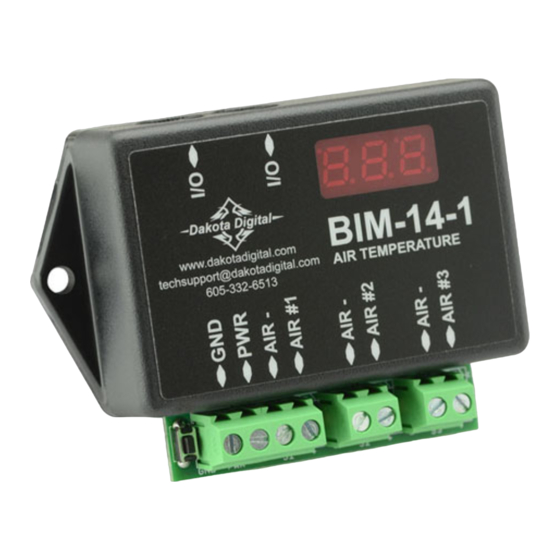
This Bus Interface Module has inputs for up to three digital air temperature sensors, SEN-15-1. Each input can be
configured individually. There are two interface ports on the module. Either one can be connected to the gauge
system or to another module, allowing several units to be daisy chained together. Do not connect the I/O port to
anything other than a Dakota Digital gauge or BIM. Do not mount the module in the engine compartment; it should be
mounted in interior of the vehicle.
Each sensor connected to the bus needs a unique ID number assigned to it. This module has three inputs so it can
use one, two, or three ID numbers. Each of the three inputs can be assigned an ID from 1 – 16, or turned off. The
factory default ID numbers are 5, 6, and OFF for the three inputs respectively. The factory default labels are
OUTSIDE, INSIDE, and INTAKE respectively.
Labels available for each input are:
OUTSIDE -
outside temperature. This will display OUTSIDE, AT (air temp), or OUTSIDE AIR TEMP.
INSIDE -
inside temperature. This will display INSIDE, IN, or INSIDE AIR TEMP.
INTAKE -
engine intake temperature. This will display INTAKE, IT, or INTAKE AIR TEMP.
Specs for each input are:
Range
-40 – 255 ° F
Temperature unit will follow the unit set for the main water temp gauge.
Sensor Mounting notes:
Make sure the sensor probe can get adequate air flow. For outside temperature measurement, the front grill area or
above the front bumper may be a good location. It should be in a location that can get good air flow across it while the
vehicle is moving. When you are sitting still for a long period of time after driving the temperature reading may begin to
rise due to the engine heat radiating forward.
Bus Interface Module for air temperature
To gauge control box
or another BIM
BIM-14-1
www.dakotadigital.com
techsupport@dakotadigital.com
AIR TEMPERATURE
605-332-6513
resolution
low warning
1° F
-24 – 40
BIM-14-1
high warning
124 – 250
Channel 3 temperature sensor
Channel 2 temperature sensor
Channel 1 temperature sensor
MAN #650348
Advertisement
Table of Contents

Subscribe to Our Youtube Channel
Related Manuals for Dakota Digital BIM-14-1


Summary of Contents for Dakota Digital BIM-14-1
- Page 1 Do not connect the I/O port to anything other than a Dakota Digital gauge or BIM. Do not mount the module in the engine compartment; it should be mounted in interior of the vehicle.
- Page 2 To set or change the ID numbers: • Hold the switch beside the BIM terminal strip while turning the key on. The BIM display will show the current revision code while this is held. • Release the switch. The display will show “-C-”. •...
- Page 3 Troubleshooting quick tips: While the BIM is operating, the dot in the upper left corner of the display will indicate the status. On steady indicates it is powered up but not receiving any bus activity. Flashing indicates it is communicating on the bus. To see the sensor and channel status on the BIM display, press and hold the switch.
- Page 4 Dakota Digital’s option. This warranty does not cover nor extend to damage to the vehicle’s systems, and does not cover removal or reinstallation of the product.
Need help?
Do you have a question about the BIM-14-1 and is the answer not in the manual?
Questions and answers