Advertisement
Quick Links
If needed, contact Dakota Digital sales to order.
•
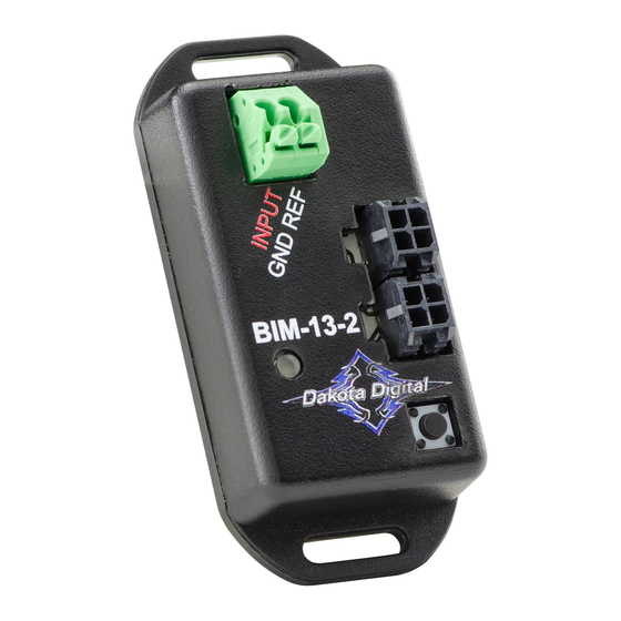
This BIM-13-2 works off a single wire input to monitor the air/fuel ratio output from a wide band air/fuel controller
with an analog voltage output.
o
Cannot read direct from an air/fuel sensor.
•
The BIM-13-2 is programmable to provide either an air/fuel ratio display or a lambda display.
•
The BIM-13-2 can be programmed to work with different scaling values of a voltage between 0 – 5 volts.
•
There are two interface (I/O) ports on the module.
o
Either one can be connected to the instrument system or to another BIM module
•
Do not connect the I/O port to anything other than a Dakota Digital control box or another BIM.
•
The BIM-13-2 should be mounted in the vehicle cabin, NOT in the engine bay.
Table of Contents:
Bus Interface Module for Air/Fuel ratio
(Requires a wide band air/fuel controller with a voltage output)
Displays, Specs, Configuration Values
VFD, and VFDX Setup
VHX Setup
HDX / RTX Setup
Changing ID Channel / Troubleshooting
Service and Warranty
[1]
BIM-13-2
Page 2
Page 3
Page 4
Page 5
Page 6
Page 8
MAN #650505D
Advertisement

Subscribe to Our Youtube Channel
Related Manuals for Dakota Digital BIM-13-2


Summary of Contents for Dakota Digital BIM-13-2
- Page 1 If needed, contact Dakota Digital sales to order. • This BIM-13-2 works off a single wire input to monitor the air/fuel ratio output from a wide band air/fuel controller with an analog voltage output. Cannot read direct from an air/fuel sensor.
- Page 2 Turn the key on so the instrument system and BIM-13-2 are powered. • Press and hold the setup/status switch on the BIM-13-2. The status light will slowly flash red and green. • After about 10 seconds the status light will begin flashing red and green rapidly. Release the switch.
- Page 3 4. Press and hold SW1 (I) until “-“ and SCAN x are displayed, a. “x” = number of BIM channels found b. If SCAN 0 is displayed, check connections of the BIM-13-2 to VFD3 control box i. If multiple BIM units are installed, follow the “Change ID” steps above to correct conflicts ii.
- Page 4 VHX setup: ✓ Ensure all desired BIM units are connected to the control box with the appropriate data cables. • Hold the SW1 (I) switch from the instrument system control box while turning the key on. The message display should show SETUP. •...
- Page 5 HDX and RTX setup: **HDX/RTX systems can be configured with the Dakota Digital app for Apple and Android devices** • Ensure all desired BIM units are connected to the control box with the appropriate data cables. • Entering Setup: HDX: After the ignition is on, press and hold both switches to enter SETUP.
-
Page 6: Quick Tips
To set or change the ID number: The ID will not normally need to be changed. A green-red-red flash on the BIM-13-2 status light indicates an ID conflict with another connected BIM. The following procedure will allow the BIM-13-2 to automatically select a new, unused ID. - Page 7 NOTES: MAN #650505D...
-
Page 8: Service And Repair
This Warranty is in lieu of all other expressed warranties or liabilities. Any implied warranties, including any implied warranty of merchantability, shall be limited to the duration of this written warranty. No person or representative is authorized to assume, for Dakota Digital, any liability other than expressed herein in connection with the sale of this product.
Need help?
Do you have a question about the BIM-13-2 and is the answer not in the manual?
Questions and answers