
Related Manuals for Keysight U4421A


Summary of Contents for Keysight U4421A
- Page 1 Keysight U4421A MIPI D-PHY Protocol Analyzer and Exerciser Hardware and Probing Guide...
- Page 2 FAR 12.211 and 27.404.2 and DFARS 227.7102, the U.S. government acquires no greater than Limited Rights as defined in FAR 27.401 or DFAR 227.7103-5 (c), as applicable in any technical data. Keysight U4421A MIPI D-PHY Analyzer and Exerciser Hardware and Probing Guide...
-
Page 3: Safety Summary
Failure to comply with these precautions or with specific warnings elsewhere in this manual violates safety standards of design, manufacture, and intended use of the instrument. Keysight Technologies Inc. assumes no liability for the customer's failure to comply with these requirements. - Page 4 Directive Annex I, this product is classed as a "Monitoring and Control instrumentation product. Do not d ispose in household waste. To return unwanted products, contact your local Keysight office, or see www.keysight.com/environment/prod uct/ for more information. Keysight U4421A MIPI D-PHY Analyzer and Exerciser Hardware and Probing Guide...
-
Page 5: About This Guide
Logic Analyzer software. • For information on how to use the U4421A module for stimulus and analysis, refer to the Keysight Logic and Protocol Analyzer software's online help. • Detailed information on Keysight probes supported for the U4421A module (such as the Keysight E5381A differential flying lead probe) is available by searching for the probe’s product number at... - Page 6 Keysight U4421A MIPI D-PHY Analyzer and Exerciser Hardware and Probing Guide...
-
Page 7: Table Of Contents
Probe Load Model for E5405A Soft Touch Probe Probe Load Model for E5381A Flying Probe 4 Setting up an E5381A Differential Flying Lead Probe Configuration for U4421A Module E5381A Differential Flying Lead Probe - Introduction When to use an E5381A Flying Lead Probe... - Page 8 Suggested Signal Routing with E5405A Probe Installing a Retention Module on the Target System Board Connecting the E5405A probe to the DUT and U4421A Module Supported Probe Configurations Index Keysight U4421A MIPI D-PHY Analyzer and Exerciser Hardware and Probing Guide...
-
Page 9: U4421A Module
Keysight U4421A MIPI D-PHY Analyzer and Exerciser Hardware and Probing Guide U4421A Module U4421A Module Hardware Components / 10 This chapter provides information on the hardware components of the U4421A module. -
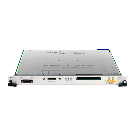
Page 10: U4421A Module Hardware Components
Keysight Logic and Protocol Analyzer GUI. For information on Keysight AXIe chassis, U4421A module, how to set up the chassis, module, and host computer and how to obtain and install the associated software components, see: "Keysight... - Page 11 U4421 Connection Setup tab of the Logic and Protocol Analyzer GUI, the number of lanes on the U4421A module are used. The LEDs of only the used lanes glow. For example, if you are using the x2 link width, then the LEDs of only two lanes being used will glow and the rest of the LEDs will be off.
- Page 12 Indicates the power-ready status of the U4421A module. This LED may turn red during the power-on-self-test phase of the chassis boot cycle. The LED then turns off when the U4421A module is in a power-ready state. The LED turns red again only when a power fault condition occurs for the module.
-
Page 13: Setting Up A Stimulus Probe Configuration For U4421A Module
Configuration for U4421A Module U4422A SMA Stimulus Probe- Introduction / 14 Connecting the U4422A Probe to the U4421A module and DUT / 16 This chapter provides information on how to connect the U4422A SMA stimulus probe with the U4421A module and DUT. -
Page 14: U4422A Sma Stimulus Probe- Introduction
U4422A SMA Stimulus Probe- Introduction The Keysight U4422A SMA stimulus probe connects the U4421A module (emulating a master D-PHY component) to the DUT. It allows you to transmit the generated digital signals from the U4421A module to the DUT. The stimulus probe can control the Link layer as well as send MIPI packets. The U4422A SMA stimulus probe has a high density module connector on one end and thirteen coaxial cables with SMA connectors on the other end. - Page 15 Emulator reference clock input positive signal Refn Red with white To U4421A module Emulator reference clock input negative signal Vsen White To U4421A module For transmitting target system supply voltage sense signal Keysight U4421A MIPI D-PHY Analyzer and Exerciser Hardware and Probing Guide...
-
Page 16: Connecting The U4422A Probe To The U4421A Module And Dut
You may leave the coaxial cables for the unused data lanes disconnected. c If you plan to configure the U4421A module to use an external reference clock, then connect the coaxial cables (labelled Refp and Refn) for accepting the external reference clock input signals. -
Page 17: Supplying External Reference Clock To The U4421A Module
U4421A module, you also need to configure the U4421A module to use the external reference clock. You do this configuration by specifying the Clock Source as External in the U4421A Setup dialog box in the Keysight Logic and Protocol Analyzer GUI. To know more, refer to the U4421A Online Help. - Page 18 Setting up a Stimulus Probe Configuration for U4421A Module Keysight U4421A MIPI D-PHY Analyzer and Exerciser Hardware and Probing Guide...
-
Page 19: Determining The Extent Of Signal Degradation With Acquisition Probes
Before you start designing the setup for a particular acquisition probing solution that you plan to use with U4421A module, you should simulate the signal integrity with that probing solution. This helps you assess the extent of signal degradation in a specific target system on attaching the probes to signals in that target system. -
Page 20: Probe Load Model For E5405A Soft Touch Probe
Determining the Extent of Signal Degradation with Acquisition Probes Probe Load Model for E5405A Soft Touch Probe Keysight U4421A MIPI D-PHY Analyzer and Exerciser Hardware and Probing Guide... -
Page 21: Probe Load Model For E5381A Flying Probe
DUT. The following screens show the circuit load model for the input impedance of the probe with various supplied accessories.. Figure 3 Equivalent probe load model when using the Coaxial Tip Resistor as the attachment accessory Keysight U4421A MIPI D-PHY Analyzer and Exerciser Hardware and Probing Guide... - Page 22 Figure 4 Equivalent probe load model when using the 3-pin header as the attachment accessory Figure 5 Equivalent probe load model when using the socket headers as the attachment accessory Keysight U4421A MIPI D-PHY Analyzer and Exerciser Hardware and Probing Guide...
- Page 23 Determining the Extent of Signal Degradation with Acquisition Probes Figure 6 Equivalent probe load model when using the damped wire as the attachment accessory Keysight U4421A MIPI D-PHY Analyzer and Exerciser Hardware and Probing Guide...
- Page 24 Determining the Extent of Signal Degradation with Acquisition Probes Keysight U4421A MIPI D-PHY Analyzer and Exerciser Hardware and Probing Guide...
-
Page 25: Setting Up An E5381A Differential Flying Lead Probe Configuration For U4421A Module
E5381A Differential Flying Lead Probe - Introduction / 26 Probe Accessories / 30 Connecting the E5381A Probe to the U4421A Module and DUT / 36 This chapter provides information on how to set up the E5381A differential flying lead probe with the... -
Page 26: E5381A Differential Flying Lead Probe - Introduction
Setting up an E5381A Differential Flying Lead Probe Configuration for U4421A Module E5381A Differential Flying Lead Probe - Introduction The E5381A is a 17-channel differential flying lead probe that you can use with the U4421A module to probe D-PHY signals. - Page 27 Description Cable Connector This component connects the E5381A probe to the U4421A module via the U4201A/N2815A cable. Flying Lead Cables This component connects the E5381A probe to the DUT via the attachment accessories supplied with the probe. There are 17 flying lead cables in each probe.
-
Page 28: D-Phy Signals To Flying Leads Mapping
Setting up an E5381A Differential Flying Lead Probe Configuration for U4421A Module The following table maps the channel number of the flying leads with their color coding and lists the D-PHY signal connection to be probed by each of these cables. - Page 29 The Data Lane 1, 2, and 3 each are probed differentially using a single channel per data lane used. The U4421A module can capture LP data and display it in "raw" mode on these data lanes. If you want to capture LP data on these lanes, then you must probe these lanes single-ended using the following signal to probe’s channel mapping:...
-
Page 30: E5381A Probe Dimensions
Setting up an E5381A Differential Flying Lead Probe Configuration for U4421A Module E5381A Probe Dimensions Figure 8 Dimensions of the E5381A probe set Figure 9 Dimensions of the E5381A flying lead tip Probe Accessories Various accessories are provided with the E5381A probe to connect the flying leads of the probe to the DUT. - Page 31 Setting up an E5381A Differential Flying Lead Probe Configuration for U4421A Module The following table lists these accessories along with their part numbers, quantity shipped, and usage. Probe Accessory Keysight Part Quantity Usage Number Shipped Coaxial Tip E5381-82101 Recommended for solder-down probing of individual test points if Resistor headers are not available on your board.
-
Page 32: Connecting The Probe Accessories To The Probe And Dut
Setting up an E5381A Differential Flying Lead Probe Configuration for U4421A Module Connecting the Probe Accessories to the Probe and DUT The following screens illustrate how to use a particular probe accessory to connect the E5381A probe’s flying leads to the DUT. - Page 33 Setting up an E5381A Differential Flying Lead Probe Configuration for U4421A Module You can probe D-Phy Data Lane 0p and Data Lane 0n using two 3-pin connectors laid side-by-side as follows: Figure 12 Using two 3-pin headers side-by-side to probe Data Lane 0 p and Data Lane 0 n There must be 0.1 inch spacing between the 3-pin headers placed side-by-side.
- Page 34 Setting up an E5381A Differential Flying Lead Probe Configuration for U4421A Module Connecting Socket Adapters Figure 13 Socket Adapter used as the probe attachment accessory You can connect multiple socket adapters side by side to pins or in tandem by skipping one NOTE or more pins but back to back connection of socket adapters to pins is not supported.
- Page 35 Setting up an E5381A Differential Flying Lead Probe Configuration for U4421A Module Connecting Damped Wires Figure 14 Damped wire used as the probe attachment accessory Keysight U4421A MIPI D-PHY Analyzer and Exerciser Hardware and Probing Guide...
-
Page 36: Connecting The E5381A Probe To The U4421A Module And Dut
Setting up an E5381A Differential Flying Lead Probe Configuration for U4421A Module Connecting the E5381A Probe to the U4421A Module and DUT The E5381A probe connects to the DUT via the supplied probing accessories and to the U4421A module via the U4201A/N2815A cable. -
Page 37: Setting Up An E5405A Soft Touch Midbus Probe Configuration For U4421A Module
E5405A Soft Touch Midbus Probe - Introduction / 38 Designing the Footprint on the DUT / 39 Installing a Retention Module on the Target System Board / 44 Connecting the E5405A probe to the DUT and U4421A Module / 46... -
Page 38: E5405A Soft Touch Midbus Probe - Introduction
The Keysight E5405A probe is a 17-channel, differential, soft touch probe that you can use with the U4421A module to probe D-PHY signals. The E5405A probe connects to the DUT via the E5403A retention module and to the U4421A module via the U4201A/N2815A cable. -
Page 39: Designing The Footprint On The Dut
Two useful configuration using this board are: • If the U4421A module is the master then place the board between the U4421A and DUT. • If the DUT is the master then place the board between the DUT and a dynamic termination board such as the University of New Hampshire - InterOperabilty Laboratory (UNH-IOL) "MIPI DPhy... - Page 40 Setting up an E5405A Soft Touch Midbus Probe Configuration for U4421A Module Figure 18 E5403A retention module dimensions Keysight U4421A MIPI D-PHY Analyzer and Exerciser Hardware and Probing Guide...
-
Page 41: Probe Pad Layout / Footprint Dimensions
Setting up an E5405A Soft Touch Midbus Probe Configuration for U4421A Module Probe Pad Layout / Footprint Dimensions The retention module alignment is symmetrical around the pad footprint. Figure 19 Top view footprint dimensions (drawing notes below). The above view is looking down onto the footprint on the printed-circuit board. -
Page 42: Pinout Details For E5405A Probe
Setting up an E5405A Soft Touch Midbus Probe Configuration for U4421A Module Surface finishes on pads should be HASL immersion silver, or gold over nickel. This footprint is compatible with Keysight model number E5403A retention module. Plated through hole should not be tied to ground plane for thermal relief. -
Page 43: Suggested Signal Routing With E5405A Probe
Setting up an E5405A Soft Touch Midbus Probe Configuration for U4421A Module Suggested Signal Routing with E5405A Probe The E5405A probe has two rows of compliant pins to make contact with pads that you laid down on the surface of the target system board. The following figure illustrates the suggested D-Phy signal routing when using the E5405A probe with the U4421A module. -
Page 44: Installing A Retention Module On The Target System Board
Setting up an E5405A Soft Touch Midbus Probe Configuration for U4421A Module You must connect the pins colored black in Figure 21 to GND on the target NOTE system. Installing a Retention Module on the Target System Board You must install an E5403A retention module on the target system board. The retention module attaches the E5405A probe to the target system board and ensures soft touch pin-to-PC board pad alignment. - Page 45 Setting up an E5405A Soft Touch Midbus Probe Configuration for U4421A Module Keysight U4421A MIPI D-PHY Analyzer and Exerciser Hardware and Probing Guide...
-
Page 46: Connecting The E5405A Probe To The Dut And U4421A Module
Setting up an E5405A Soft Touch Midbus Probe Configuration for U4421A Module Connecting the E5405A probe to the DUT and U4421A Module The E5405A probe connects to the DUT via a retention module and to the U4421A module via the U4201A/N2815A cable. - Page 47 U4201A cable, 36, 38, flying lead colors, U4305A exerciser card, flying lead tip, U4421A analysis port, 36, U4422A SMA stimulus probe, grounding, 29, 36, Vsen, 15, 16, Keysight U4421A MIPI D-PHY Analyzer and Exerciser Hardware and Probing Guide...
- Page 48 Index Keysight U4421A MIPI D-PHY Analyzer and Exerciser Hardware and Probing Guide...
Need help?
Do you have a question about the U4421A and is the answer not in the manual?
Questions and answers