
Related Manuals for CLIVET WSAR-MT Series


Summary of Contents for CLIVET WSAR-MT Series
- Page 1 WSAR-MT 21-25-31-41-51-61-81 AIR-WATER HEAT PUMP FOR OUTDOOR INSTALLATION Installation and Use Manual M0G440G8-00 02/09/2008...
-
Page 3: Table Of Contents
U N I T I D E N T I F I C A T I O N ................4 I N S T R U C T I O N S F O R T H E U S E R . -
Page 4: Unit Identification
UNIT IDENTIFICATION SERIAL NUMBER LABEL The units are identified by the serial number label shown here. The label lists the type of unit (series and size), serial number, year of manufacture, number of electrical diagram, main technical data, logo and address of the manufacturer. The label is placed on the unit, generally near the electrical panel and also on the external panelling. -
Page 5: Instructions For The User
INSTRUCTIONS FOR THE USER • This is a partial shyntesis of the information provided in the manual; carefully read this manual • Carefully read this manual. Keep it with the electrical diagram. Make it available to technicians for servicing. • Ask the installer for training on start-up, shutdown, changing set points, placing in at-rest status, maintenance, what to do or not to do in the event of a breakdown. -
Page 6: General Warnings
Perform the operations in conformity with the local CE MARK regulations in force. Clivet products bear the CE mark, in compliance with the PERIODICAL INSPECTIONS requirements of the following EC directives, including the Perform periodical inspections to locate possible loosened latest amendments, and with the corresponding national or broken parts. -
Page 7: Residual Risks
RESIDUAL RISKS and precaution is taken when positioning and securing the GENERAL unit. This section lists some of the more common situations If the unit is easily accessible to children, unauthorized which, being beyond the control of the manufacturer, could persons or animals, this is a situation that can give rise be a source of risk to persons or property. - Page 8 Contact with parts that could become live when the unit is injured or suffer toxic effects. Always wear suitable clothing started up can result in electric shock, burns or death by and protective goggles when working in potential hazard electrocution. areas.
- Page 9 Chemical -physical Relative density, gas (air=1) Heavier than air. properties. Solubility in water (mg/l). Not known, but probably very low. Aspect. Colorless liquefied gas. Smell. Simile to ether. Point of ignition. Don’t ignite. Stability and Stability and reactivity. No decomposition if used following the instructions. reactivity.
-
Page 10: R E C E P T I O
RECEPTION Before starting the handling operations: INSPECTION UPON RECEPTION • Value the critical points during handling (stairs, flights, Check on arrival that the unit has not suffered damage disconnected routes, doors, etc) during transit and that it is complete in every part as •... -
Page 11: P O S I T I O N I N
POSITIONING Verify that the fixing/supporting points are level and GENERAL suitable to support the weight of the unit (see the For installing air-conditioning systems, it is necessary to weight and the weights distribution) consider the following: • the technical spaces necessary for the machine and It is recommended to put the unit on specific system antivibration devices... - Page 12 ACCESS TO THE UNIT INTERIOR To access to the unit interior remove in sequence : lower lateral panels upper lateral panels the casing Coupling points for panels Removable panels and casing Electrical panel that can be opened and casing M0G440G8-00 03/09/08 page 12...
-
Page 13: W A T E R C O N N E C T I O N
WATER CONNECTIONS CONNECTIONS SUPPORTS GENERAL The weight of the hydraulic connections must be supported Piping must be designed with the least possible number of in the exterior of the unit so as not to stress the connections bends and head variations. If the pressure chute of the of user devices (exchangers, coils, humidifiers, etc ) . -
Page 14: Winter Condensation
INPUTS To perform water / electrical connections remove first the plate cover ( 1 ) In case of unit lower input , use the pre-cutting hole on the base plate ( B ) Kit idronico: Unit water and electrical connections Optional hydronic kit A Lateral output input for water circuit circulating pump... -
Page 15: E L E C T R I C A L C O N N E C T I O
ELECTRICAL CONNECTION the unit; the electrical data shown in the technical chart GENERAL refer to standard units. In the event of differences between The characteristics of the electrical lines and relevant the data of the registration plate and the data shown in this components must be determined by SPECIALIZED manual, as well as in the technical chart, please refer to the PERSONNEL ABLE TO DESIGN ELECTRICAL... -
Page 16: Connection To The Mains
ACCESSORY ELECTRICAL DATA Sizes Circulating pump data F.L.A. – Circulating pump 0,95 0,95 1.24 1.24 1.24 3.20 3.20 F.L.I. - Circulating pump 0,20 0,20 0,26 0.26 0.26 0.66 0.66 Integration resistance data F.L.A. - Integration resistance 26.08 26.08 26.08 26.08 F.L.A. - Page 17 Costumer connection terminal block Remote ON – OFF: S A 1 XC 2 Remote second set : S A 3 Remote Summer – Winter: S A 2 The second setpoint is used to reduce the energy The Summer-Winter operating mode can be chosen consumptions (ex.
- Page 18 Domestic hot water request : S A 4 EXT. 3-WAY VALVE 230/1/50 XC 1 For the production of domestic hot water the 3-way valve must be present. For details see on the side . For the production of domestic hot water the 3-way valve When the production of domestic hot water is active, it is must be present .
- Page 19 SET POINT CORRECTION WATER RESET ON OUTSIDE TEMPERATURE and HUMIDITY XC 2 XC 2 4-20 mA SUMMER WINTER With low outside With mild outside SUMMER WINTER temperatures the refrigerant temperatures the thermal If the refrigerant needs is If the thermal needs is low, needs is reduced.
- Page 20 CLIVET BUS connection MODBUS connection max 50 mt - standard max 1000 mt - optional 230/1/50 RS485 SYSTEM MANAGER DIP 2 Necessary configuration if are present the domestic hot DIP 3 water module or the mixing module for radiant panels...
-
Page 21: S T A R T - U
START-UP ALL THE EQUIPMENT MUST BE COMMISSIONED BY AUTHORISED SERVICE CENTRES. THIS SERVICE IS LIMITED TO START-UP OF THE UNIT ONLY AND NOT THE CONNECTIONS OR INSTALLATION OF THE SYSTEM. ONLY QUALIFIED TECHNICIANS MUST PERFORM THE FOLLOWING OPERATIONS. Charge the unit by closing the sectioning device, but leave PRELIMINARY CHECKS it on OFF. -
Page 22: Remote Input Configurations
thermal protection. In this event, cut the power and reverse Check for water side exchanger pressure drops: the 2 phases on the machine power. • Determine the water flow rate. Prevent the compressor from working with in reverse • Measure the difference in pressure between rotation: more than 2-3 anomalous starts up can damage it. -
Page 23: C O N T R O
CONTROL HEAT / COOL – EXIT (previous menu) ALARMS / AHEAD fast menu STATA / BACK fast menu ON / OFF – MAIN MENU ENTER : access to menu AHEAD BACK slow switch on / switch off : the unit comfort / economic : choose between max. - Page 24 It appears the new chosen status ( ECO ) COOL / HEAT / produce DOMESTIC HOT WATER Press the button Rotate the button to scroll the menu Press the button to confirm the choice Cooling Heating It appears the symbol of the new choice Domestic hot water production TO MODIFY THE SET...
- Page 25 UNIT KEYPAD mode Access to menu UP – DOWN main menu previous menu main menu base FW version stata keypad FW version unit stata stata I/O digital inputs analogical inputs digital outputs analogical outputs active alarms alarms alarm log alarm reset log reset keypad setup...
- Page 26 CHRONOTHERMOSTAT – SYSTEM MANAGER mode accesso menu UP – DOWN main menu previous menu main menu keypad FW version stata unit stata heat pump ACS module terminals heat pump alarms ACS module terminals keypad setup configuration setpoint language zones sanitary setup antilegionella system...
- Page 27 IN CASE OF ALARM The ALARMS indicates a potentially dangerous situation for the unit integrity. Before resetting the alarm, identify and remove the lockout cause. Resetting more than once can cause irreversible damages . In case of doubt please contact an authorized service centre. Active alarms Alarm description Press to see the alarm...
-
Page 28: Alarm
LIST OF ALARMS Reset Electrical Alarm Description Refrigerant Manual Prealarm Hydraulic Automatic E 00 Base keypad Timeout E/R/H E 01 Input temp. probe utility side E 02 Supply temp. probe utility side E 03 Outside temp. probe E 04 Coil/output temp. probe source E 05 Return temp. -
Page 29: S T A T
CHECK THE STATA ( water and air temperatures, etc ) Press to access to the STATA menu STATA S1 xxxx than S2 XXXX ⇒ rotate to scroll . The complete stata list is at the following page Press to go back to the main panel Or : MAIN MENU Press to access to the MAIN menu... - Page 30 UNIT STATA Num. status DESCRIPTION Current Set point °C Current step difference (with compensations) °C Resource insertion timer Seconds Dynamic TimeScan of the resource insertion Seconds Outside T compensation °C Ambient T compensation °C WR compensation °C Charge compensation °C Duty Cycle compensation °C Compensation on duration...
-
Page 31: R O U T I N E M A I N T E N A N C
ROUTINE MAINTENANCE BEFORE UNDERTAKING ANY SORT OF MAINTENANCE OR CLEANING, DISCONNECT THE ELECTRICAL POWER SUPPLY TO THE UNIT, AND ENSURE THAT OTHER PEOPLE CANNOT RE-CONNECT IT . All equipment is subjected to wear out. The machine should have a log book used to keep track of the performed controls. -
Page 32: Maintenance Inspections
MAINTENANCE INSPECTIONS Foresee inspection assistance carried out by authorized The inspections to be performed are as follows: centers or by qualified personnel. • verify the power supply tension (when emptied or filled) The inspections should be carried out at least: •... -
Page 33: Refrigerant Tables
REFRIGERANT TABLES THIS SECTION IS DEVOTED ONLY TO QUALIFIED TECHNICIANS THAT KNOW THE FOLLOWING: • THE OPERATIONAL PRINCIPLES OF THE REFRIGERATING CIRCUIT OPERATION • THE MODES OF DETECTING TEMPERATURE AND PRESSURE • THE RISKS RELEVANT TO THESE OPERATIONS The data of the tables allow the testing of the refrigerating circuit operation by the detection of a few objective parameters. The data are significant if they are detected simultaneously and while the refrigerating circuit is running. -
Page 34: T R O U B L E S H O O T I N
TROUBLESHOOTING THE OPERATIONS MUST BE CARRIED OUT BY TECHNICAL QUALIFIED PERSONNEL HAVING THE REQUISITES UNDER LAW REQUISITES AND IN CONFORMITY WITH THE SAFETY REGULATIONS IN FORCE. THE INTERVENTIONS WITHIN THE WARRANTY PERIOD WILL BE CARRIED OUT BY AUTHORIZED SERVICE CENTERS. BEFORE RESETTING AN ALARM, IDENTIFY AND ELIMINATE ITS CAUSE. - Page 35 FAN PROTECTION COMPRESSOR PROTECTION Identify the part on the wiring diagram Identify the part on the wiring diagram fan mechanically jammed, bearings / drive belt (if Loose electric contacts/terminals, leads broken present) electrical windings interrupted Loose electric contacts/terminals, leads broken Vacuum power voltage below the limits electrical windings of fan interrupted power contactors / contacts defective...
-
Page 36: D E C O M M I S S I O N I N G O F T H E U N I
DECOMMISSIONING OF THE UNIT Awaiting dismantling and disposal, the unit can also be DISCONNECTING THE UNIT stored outdoors, as bad weather and rapid changes in The units must be disconnected by authorised personnel, temperature will not cause damage to the environment, if who before proceeding must first read the Residual Risks electric, cooling and hydraulic circuits of the unit are section in this manual. -
Page 37: Technical Data
TECHNICAL DATA M0G440G8-00 03/09/08 page 37... - Page 38 TECHNICAL DATA BASE CONFIGURATION Sizes 400/3/50+N Heating A7(6)W30/35 Heat capacity 6.13 8.16 10.0 11.2 14.0 17.7 22.9 Total absorbed capacity 1.57 2.05 2.51 2.87 3.55 4.42 5.87 COP EUROVENT 3.95 4.03 4.03 3.96 4.00 4.06 3.96 COP EN14511 3.91 3.98 3.98 3.90 3.94...
- Page 39 OPERATING LIMITS Sizes COOLING EXTERNAL EXCHANGER Input air max. temperature °C INTERNAL EXCHANGER Output water max. temperature °C Output water min. temperature °C HEATING EXTERNAL EXCHANGER Input air max. temperature °C Input air min. temperature °C INTERNAL EXCHANGER Output water min. temperature °C Output water max.
- Page 40 SOUND LEVELS Sound Sound Power Level (dB) Sound power pressure Measures according to EN 3744 regulations, level Size level Octave band (Hz) with respect to the EUROVENT 8/1 certification. 125 250 500 1000 2000 4000 8000 dB(A) dB(A) The sound pressure is measured at 1 m from the external surface of the unit in open field conditions.
-
Page 41: Dimensions
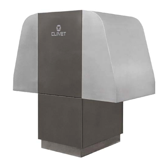
DIMENSIONS (1) condensate discharge (2) installation input (3) installation output (4) domestic hot water input (5) domestic hot water output (6) installation charge (7) power input (8) E.P. and maintenance (9) outlet air direction (10) inlet air direction (11) compressor (12) finned exchanger (13) fan SIZE... - Page 44 The data contained in this bulletin is not binding and may be changed by the manufacturer without prior notice. All reproduction, even partial, is PROHIBITED. © COPYRIGHT - CLIVET S.P.A. - FELTRE (BL) - ITALIA...
Need help?
Do you have a question about the WSAR-MT Series and is the answer not in the manual?
Questions and answers