Table of Contents
Advertisement
Advertisement
Table of Contents

Related Manuals for Cisco Cisco 5400 ENCS


Summary of Contents for Cisco Cisco 5400 ENCS
- Page 1 Cisco 5400 Enterprise Network Compute System Hardware Installation Guide First Published: 2017-03-02 Last Modified: 2018-04-20 Americas Headquarters Cisco Systems, Inc. 170 West Tasman Drive San Jose, CA 95134-1706 http://www.cisco.com Tel: 408 526-4000 800 553-NETS (6387) Fax: 408 527-0883...
- Page 2 Cisco has more than 200 offices worldwide. Addresses and phone numbers are listed on the Cisco website at www.cisco.com/go/offices. Cisco and the Cisco logo are trademarks or registered trademarks of Cisco and/or its affiliates in the U.S. and other countries. To view a list of Cisco trademarks, go to this URL: www.cisco.com...
-
Page 3: Table Of Contents
Obtaining Documentation and Submitting a Service Request C H A P T E R 1 Overview of the Cisco 5400 Enterprise Network Compute System About the Cisco 5400 Enterprise Network Compute System Cisco 5400 Series Enterprise Network Compute System Chassis... - Page 4 Mixing Drive Types in RAID Groups Disks Replacement Considerations RAID Backup Units Installing ENCS-MRAID Drivers for NFVIS RAID Configuration JBOD Mode RAID-1 Mode Secured RAID Group Configuration JBOD Secured Mode RAID-1 Secured Mode Cisco 5400 Enterprise Network Compute System Hardware Installation Guide...
- Page 5 Contents RAID Disk Group Rebuild For More Information Cisco 5400 Enterprise Network Compute System Hardware Installation Guide...
- Page 6 Contents Cisco 5400 Enterprise Network Compute System Hardware Installation Guide...
-
Page 7: Preface
What's New in Cisco Product Documentation. To receive new and revised Cisco technical content directly to your desktop, you can subscribe to the What's New in Cisco Product Documentation RSS feed. RSS feeds are a free service. - Page 8 Preface Obtaining Documentation and Submitting a Service Request Cisco 5400 Enterprise Network Compute System Hardware Installation Guide viii...
-
Page 9: Overview Of The Cisco 5400 Enterprise Network Compute System
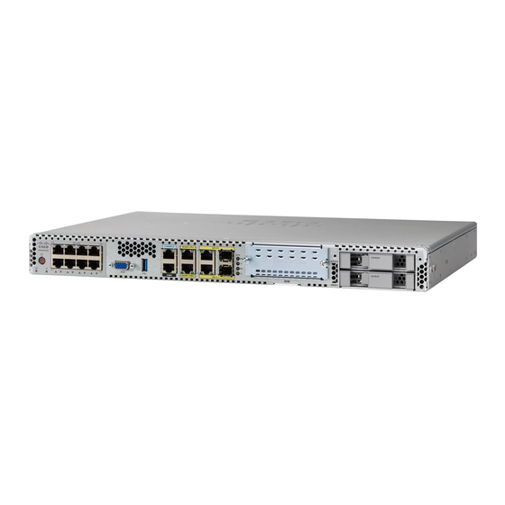
Models, on page 14 About the Cisco 5400 Enterprise Network Compute System The Cisco 5400 Enterprise Network Compute System (ENCS) combines routing, switching, storage, processing, and a host of other computing and networking activities into a compact one Rack Unit (RU) box. This high-performance unit achieves this goal by providing the infrastructure to deploy virtualized network functions while at the same time acting as a server that addresses processing, workload, and storage challenges. -
Page 10: Chassis - Bezel Side
Drive bay 1 Ethernet management port for CIMC Serial console port for CIMC Chassis - Bezel Side Figure 2: Bezel View of the Cisco 5400 ENCS Fan vents Modular power supply Removable bezel Cisco 5400 Enterprise Network Compute System Hardware Installation Guide... -
Page 11: Chassis - Internal View
Overview of the Cisco 5400 Enterprise Network Compute System Chassis - Internal View Chassis - Internal View Figure 3: Internal View of the Cisco 5400 ENCS Table 1: PoE daughter card Modular power supply DDR4 DIMM slots on motherboard - 2 RAID card M.2 storage module on motherboard... - Page 12 Electrical Appliance and Material Safety Law prohibits the use of certified cables (that have the ‘UL’ shown on the code) for any other electrical devices than products designated by Cisco. The use of cables that are certified by Electrical Appliance and Material Safety Law (that have ‘PSE’ shown on the code) is not limited to Cisco-designated products.
- Page 13 Overview of the Cisco 5400 Enterprise Network Compute System Safety Warnings Warning This unit may have more than one power supply connection. All connections must be removed to de-energize the unit. Statement 1028 Warning This equipment must be grounded. Never defeat the ground conductor or operate the equipment in the absence of a suitably installed ground conductor.
- Page 14 Overview of the Cisco 5400 Enterprise Network Compute System Safety Warnings Warning To prevent the system from overheating, do not operate it in an area that exceeds the maximum recommended ambient temperature of: 40 degrees C. Statement 1047 Warning Blank faceplates and cover panels serve three important functions: they prevent exposure to hazardous voltages and currents inside the chassis;...
-
Page 15: Hardware Features - Standard
• VGA connector: You can use this port to connect a monitor to the device. It supports a display resolution of up to 1600 x 1200 16bpp @ 60Hz. • Ethernet management port for CIMC: Cisco Integrated Management Controller (CIMC) is the component in the device that monitors the health of the entire system. - Page 16 Overview of the Cisco 5400 Enterprise Network Compute System Hardware Features - Standard Figure 4: LEDs for Gigabit Ethernet Ports The LEDs labeled EN indicates whether the corresponding ports are enabled. The frequency of the blinks of the LEDs labeled S shows the speed of the corresponding ports. This table maps the blink frequency of a LED to the speed of the corresponding port.
- Page 17 Overview of the Cisco 5400 Enterprise Network Compute System Hardware Features - Standard Table 2: Front Panel LED Status LED Label Color Behavior System boot LED Amber BMC boot complete, Intel powered down Blinking amber BMC booting, Intel powered down...
- Page 18 Overview of the Cisco 5400 Enterprise Network Compute System Hardware Features - Standard LED Label Color Behavior WAN port speed LED Blinking green Blink frequency indicates port speed: 1 blink - 10 Mbps link speed 2 blink - 100 Mbps link...
- Page 19 Overview of the Cisco 5400 Enterprise Network Compute System Hardware Features - Standard Bazel Side LED Status Table 3: Bazel Side LED Status LED Label Color Behavior RAID status Blue RAID card is present and working Amber RAID card is present and...
-
Page 20: Hardware Features - Replaceable And Upgradable Units
PSU in failure mode. Hardware Features - Replaceable and Upgradable Units The replaceable and upgradable units of the Cisco 5400 ENCS are: • Power supply: The power supply provides AC power. The ENCS5406/K9 device supports only the non-PoE power supply option. This means the LAN ports of this device cannot provide Power over Ethernet (PoE). - Page 21 Overview of the Cisco 5400 Enterprise Network Compute System Hardware Features - Replaceable and Upgradable Units Table 4: Supported NIMs Product Module Minimum Software NIM-4G-LTE-VZ NFVIS 3.6.1 ISRv 16.6.1 NIM-4G-LTE-ST NIM-4G-LTE-NA NIM-4G-LTE-GA NIM-4G-LTE-LA NIM-LTEA-EA NIM-LTEA-LA NIM-1MFT-T1/E1 NFVIS 3.6.1 T1/E1 Data ISRv 16.6.1...
-
Page 22: Models
CIMC 3.2.3 3.2.3 3.2.3 3.1.4 Models The Cisco 5400 ENCS is available in these models: Product ID Description ENCS5406/K9 This device has a 6 core CPU. This system does not support a PoE power supply. Cisco 5400 Enterprise Network Compute System Hardware Installation Guide... - Page 23 Overview of the Cisco 5400 Enterprise Network Compute System Models Product ID Description ENCS5408/K9 This device has an 8 core CPU. ENCS5412/K9 This device has a 12 core CPU. Note With the exception of the CPU capacity and the power supply unit, all other hardware features (standard, replaceable and upgradable) are common across all models.
- Page 24 Overview of the Cisco 5400 Enterprise Network Compute System Models Cisco 5400 Enterprise Network Compute System Hardware Installation Guide...
-
Page 25: Preparing For Installation
Safety Recommendations and Warnings Please read the following safety guidelines before you install this product: • Review the safety warnings listed in Regulatory Compliance and Safety Information for the Cisco 5400 Enterprise Network Compute System before installing, configuring, or maintaining the device. -
Page 26: Site Requirements
Site Requirements Follow the general precautions listed below when installing or working with your device: • Keep your system components away from radiators and heat sources. • Do not block cooling vents. Cisco 5400 Enterprise Network Compute System Hardware Installation Guide... - Page 27 Power off other equipment in the rack (and in adjacent racks) to allow the equipment to be tested in a condition that has maximum cool air and clean power. Cisco 5400 Enterprise Network Compute System Hardware Installation Guide...
-
Page 28: Mounting Requirements
To place the system in a proper location, it is necessary to know the dimensions of the device's chassis. The Cisco 5400 ENCS can be placed on a desktop or installed in a rack. The mounting ears for the device are designed for #12-24 UNC screws. -
Page 29: Network Cabling Specification
• Cables for connection to the WAN and LAN ports (dependent on the configuration) Note If you order the required cables when you purchase the device, the cables ship along with the product. Cisco 5400 Enterprise Network Compute System Hardware Installation Guide... - Page 30 Preparing for Installation Required Tools and Equipment Cisco 5400 Enterprise Network Compute System Hardware Installation Guide...
-
Page 31: Installing The Device
• Locating the Product ID, Serial Number, Version ID and Common Language Equipment Identifies (CLEI), on page 23 • Installing the Cisco 5400 ENCS, on page 24 • Powering On the Server, on page 27 • Initial Server Setup, on page 27 Unpacking the Device The device, accessory kit, publications, and any optional units may be shipped in more than one container. -
Page 32: Installing The Cisco 5400 Encs
NIM and HDDs either before or after you mount the chassis. Rack-Mounting the Chassis The Cisco 5400 ENCS can be installed in 19-inch (48.26-cm) racks. Use the standard brackets shipped with the router for mounting the chassis in a 19-inch EIA rack. - Page 33 The screws for attaching the device to the rack are not provided with the kit. Cisco 5400 Enterprise Network Compute System Hardware Installation Guide...
-
Page 34: Wall-Mounting The Chassis
Depending on the type of wall (wood, brick, stone etc), use appropriate screws to fix the device to the wall. Note Route the cables so that they do not put a strain on the connectors or mounting hardware. Cisco 5400 Enterprise Network Compute System Hardware Installation Guide... -
Page 35: Powering On The Server
Initial Server Setup Local Connection Procedure 1. Ensure that the device is powered on. Cisco 5400 Enterprise Network Compute System Hardware Installation Guide... - Page 36 2. Telnet into the console and perform the necessary configuration using corresponding commands. You can also configure the IP address for the Ethernet CIMC port. Use CIMC to configure the box. For more details, see Initial Setup for UCS C-Series Servers. Cisco 5400 Enterprise Network Compute System Hardware Installation Guide...
-
Page 37: Installing And Upgrading Frus
4. Remove the screws at the sides of the device (See Figure 11). 5. Lift the chassis cover once you have removed all the screws. Figure 10: Removing the Chassis Cover Cisco 5400 Enterprise Network Compute System Hardware Installation Guide... -
Page 38: Replacing The Power Supply
These are the steps to install a drive in a drive bay: 1. The drive bays are in the front panel of the device. The bays are closed with a cover if there are no drives in the slots. Cisco 5400 Enterprise Network Compute System Hardware Installation Guide... -
Page 39: Upgrading The M.2 Storage Module
3. Remove the old storage module by unscrewing the screw that secures the hardware and removing out the storage module. 4. Plug in the new storage module in the same location and secure it with the screw. Cisco 5400 Enterprise Network Compute System Hardware Installation Guide... -
Page 40: Installing And Removing A Dimm
There are two DDR4 DIMM slots. DIMMs have a polarization notch on the connecting edge to prevent incorrect insertion. Figure 14: DIMM Showing Polarization Notch These are the steps to install a DIMM: 1. Remove the chassis cover. 2. Locate the DIMM module on the device. Cisco 5400 Enterprise Network Compute System Hardware Installation Guide... - Page 41 3. Make sure that both latches on the DIMM connector are in the open position. 4. Orient the DIMM so that the polarization notch lines up with the polarization key on the connector. 5. Insert the DIMM into the connector. Cisco 5400 Enterprise Network Compute System Hardware Installation Guide...
- Page 42 3. Pull the latches away from the DIMM at both ends to lift the DIMM slightly. Pull the DIMM out of the socket. Figure 17: Removing a DIMM 4. Place the DIMM in an antistatic bag to protect it from ESD damage. 5. Replace the chassis cover. Cisco 5400 Enterprise Network Compute System Hardware Installation Guide...
-
Page 43: Installing And Removing A Nim
Proceed with stop of module? [confirm] CSR-8# CSR-8# CSR-8#sh platform Chassis type: ISRV Slot Type State Insert time (ago) --------- ------------------- --------------------- ----------------- ISRV 16:41:27 NIM-4G-LTE-NA stopped 00:00:05 ISRV ok, active 16:42:19 ISRV ok, active 16:42:19 Cisco 5400 Enterprise Network Compute System Hardware Installation Guide... - Page 44 Installing and Upgrading FRUs Installing and Removing a NIM Cisco 5400 Enterprise Network Compute System Hardware Installation Guide...
-
Page 45: Supported Raid Controllers And Required Cables
3 When using SED drive. RAID Cabling Cisco ENCS-MRAID card does not require additional cable to connect hard drives and RAID card. The flex cable connected to the mainboard can be used to connect to RAID card. RAID Card LED Indicator When RAID card is installed, the LED indicator in the front bezel should turn in solid green. -
Page 46: Raid Card Firmware Compatibility
Host Upgrade Utility (HUU) for your firmware release to bring it to a compatible level. See the HUU guide for your Cisco IMC release for instructions on downloading and using the utility to bring server components to compatible levels:... -
Page 47: Drive Types And Sizes Supported
The following table lists the technical capabilities for mixing hard disk drive (HDD) and solid state drive (SSD) types in a RAID group. However, see the recommendations that follow for the best performance. Cisco 5400 Enterprise Network Compute System Hardware Installation Guide... -
Page 48: Disks Replacement Considerations
• - Do not swap the drives between Slot-0 and Slot-1. • - Do not swap or replace drives used by other ENCS system without reformatting it beforehand. RAID Backup Units ENCS-MRAID does not support RAID backup units. Cisco 5400 Enterprise Network Compute System Hardware Installation Guide... -
Page 49: Installing Encs-Mraid Drivers For Nfvis
• If disk is in JBOD state: go to Storage tab > Physical Drive Info tab, choose Set State as Unconfigured Good link for this drive. • If disk is in Foreign Config state, go to Storage tab > Controller Info tab, choose Clear Foreign Config in Action field. Cisco 5400 Enterprise Network Compute System Hardware Installation Guide... -
Page 50: Secured Raid Group Configuration
Use CIMC CLI to enable security with following steps: SUMMARY STEPS 1. Log into CIMC. 2. Under CIMC CLI shell, issues the following CLI: 3. Verify that controller’s security is enabled. Cisco 5400 Enterprise Network Compute System Hardware Installation Guide... -
Page 51: Jbod Secured Mode
• From CIMC CLI, issue the following CLI: ENCS5408-FGL210310KJ /chassis/storageadapter # show physical-drive 1 detail Physical Drive Number 1: Controller: SLOT-5 Health: Good Status: JBOD Boot Drive: false Manufacturer: HGST Model: HUC101812CSS205 Cisco 5400 Enterprise Network Compute System Hardware Installation Guide... -
Page 52: Raid-1 Secured Mode
Unlike the security-disabled configuration, different controller has different encryption key, please advise your system administrator with the following conditions: • Replacing ENCS-MRAID controller will render FDE-enabled disks data un-retrievable on same host. • FDE-enabled disks cannot be swapped between systems. Cisco 5400 Enterprise Network Compute System Hardware Installation Guide... -
Page 53: Raid Disk Group Rebuild
• • For hardware SAS MegaRAID - Avago Technologies/LSI 12 Gb/s MegaRAID SAS Software User’s Guide, Rev. F • • For embedded software MegaRAID - LSI Embedded MegaRAID Software User Guide Cisco 5400 Enterprise Network Compute System Hardware Installation Guide... - Page 54 Supported RAID Controllers and Required Cables For More Information Cisco 5400 Enterprise Network Compute System Hardware Installation Guide...
Need help?
Do you have a question about the Cisco 5400 ENCS and is the answer not in the manual?
Questions and answers