Advertisement
Quick Links
F
I
T
N
O
R
D
C
Y
C
L
O
2
0
0
R
F
I
T
N
O
R
D
C
Y
C
L
O
2
0
0
R
R
E
C
U
M
B
E
N
T
R
E
C
U
M
B
E
N
T
OWNER'S MANUAL
IMPORTANT!
Please read all instructions carefully before using this product.
Retain this manual for future reference.
The specifications of this product may vary slightly from the illustrations and are subject to
change without notice.
Advertisement

Subscribe to Our Youtube Channel
Related Manuals for FitNord CYCLO 200R


Summary of Contents for FitNord CYCLO 200R
- Page 1 OWNER’S MANUAL IMPORTANT! Please read all instructions carefully before using this product. Retain this manual for future reference. The specifications of this product may vary slightly from the illustrations and are subject to change without notice.
-
Page 2: Important Safety Notice
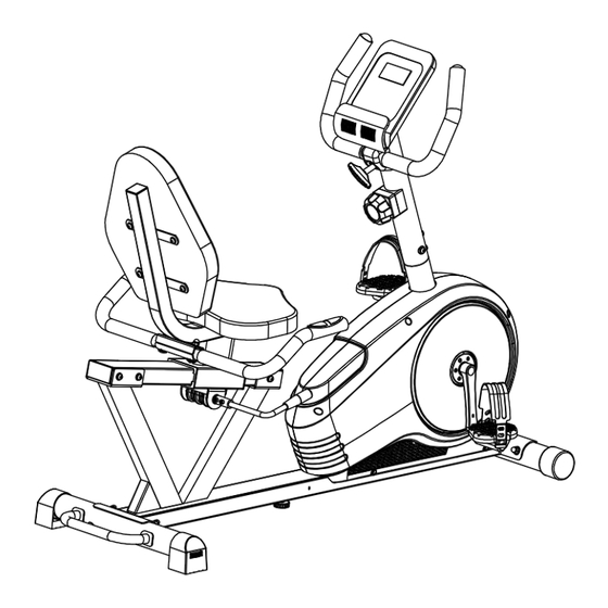
Before You Start Thank you for purchasing this Bike! For your safety and benefit, read this manual carefully before using the machine. Prior to assembly, remove components from the box and verify that all the listed parts are supplied. Assembly instructions are described in the following steps and illustrations. IMPORTANT SAFETY NOTICE PRECAUTIONS BE SURE TO READ THE ENTIRE MANUAL BEFORE YOU ASSEMBLE OR OPERATE YOUR MACHINE. -
Page 3: Exploded Diagram
EXPLODED DIAGRAM - 2 -... -
Page 4: Parts List
PARTS LIST Q’TY Q’TY DESCRIPTION DESCRIPTION Main frame Foam grip Seat frame Square end cap 38x38x1.5 Handlebar Square end cap 80x40x2 Guide rail Bushing Handlebar post Bracket Front stabilizer Saddle Rear stabilizer Backrest Handle Plug Carriage bolt M8×L76 Round end cap Carriage bolt M8×L45 40L/R Crank Acorn nut M8... - Page 5 ASSEMBLY INSTRUCTIONS STEP 1: 1. Lock the Lifting handle (49) to the Rear stabilizer (7) with Allen screws (50), Spring washers (13) and Arc washers (12). 2. Attach the Front stabilizer (6) and Rear stabilizers (7) to the Main frame (1) with Carriage bolts (9), Spring washers (13), Arc washers (12) and Acorn nuts (11).
- Page 6 STEP 3: 1. Connect Extension pulse wire 2 (45) with Extension pulse wire 1 (42). 2. Feed the Tension wire (52) through the hole in the Handlebar post (5) 3. Connect the Tension wire (52) with the Tension controller (23) as shown in picture A. 4.
- Page 7 STEP 4: 1. Attach the Handlebar (56) to the Handlebar post (5) with the Plastic handle knob (53), Handlebar cover (54), Spacer (55) and Washer (15). 2. Connect the Extension pulse wire 2(45) and Extension sensor wire (30) with the Computer (44) wires 3.
- Page 8 STEP 5: 1. Insert the Guide rail (4) into the Seat frame (2) 2. Attach the Guide rail (4) to the Main frame (1) with Allen screws (14), Spring washers (13) and Washers (15). - 7 -...
- Page 9 STEP 6: 1. Insert the Handle (8) into the Eccentric shaft (19) and lock with Hex bolts (22). 2. Insert the Handlebar (3) into the Seat frame (2) and lock with Carriage bolts (10), Washers (15) and Acorn nuts (11). 3.
Need help?
Do you have a question about the CYCLO 200R and is the answer not in the manual?
Questions and answers