Table of Contents

Related Manuals for Waterous Pressure Governor


Summary of Contents for Waterous Pressure Governor
- Page 1 Form Number: F-2837 Issue Date: Aug 12, 2020 Revision Date: Nov 9, 2020 Pressure Governor System Installation and Operation Waterous Company • 125 Hardman Avenue South • South Saint Paul, MN 55075 • (651) 450-5000 www.waterousco.com...
-
Page 3: Table Of Contents
Connecting the Cable—Power, Alarm, SAE CAN (J1939), and Inlet Pressure Sensor Connecting the Cable—Power, Alarm, SAE CAN (J1939), IC CAN (J1939), and Inlet Pressure Sensor Configuring the Pressure Governor—User Configuration Mode Configuring the Pressure Governor—Service Configuration Mode Configuring the Pressure Governor—OEM Configuration Mode... - Page 4 Operation Pressure Governor Operation Pressure Mode Speed Mode Idle Mode High-Idle Mode Display Messages...
-
Page 5: Safety
• Be aware that these instructions are only guidelines and are not meant to be Before Operation definitive. Contact Waterous when you have questions about installing, operating, or maintaining the equipment. • Do not install the equipment if you are not familiar with the tools and skills •... -
Page 6: Introduction
Installation Operation Using this Document Use this document to install and operate your Waterous equipment. Understand the following conditions before continuing with the document: Use the guidelines below when viewing this document. • The instructions may refer to options or equipment that you may not have Viewing the Document Electronically purchased with your system. -
Page 7: System Overview
Operation System Overview The Waterous pressure governor uses various apparatus inputs to control the engine speed and discharge pressure. Additional control and information is available through configuration settings and cable selection. Operating modes are available when interlock settings permit. Pressure Mode... - Page 8 Notes...
-
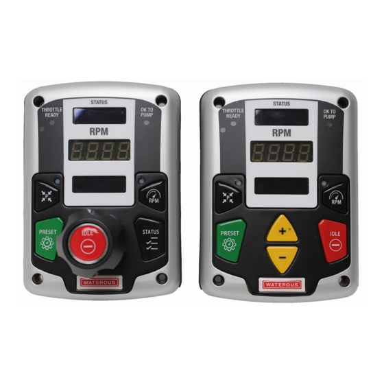
Page 9: Pressure Governor-Rotary Style
Safety Introduction Product Overview Installation Operation Pressure Governor—Rotary Style... - Page 10 13 Battery voltage indicator This uses 3 colors to indicate the apparatus voltage as measured by the pressure governor dc input. The colors are: green=12.5 V or greater, yellow=11.9–12.5 V, red=11.8 or less. You can configure a voltage drop offset if needed.
-
Page 11: Pressure Governor-Button Style
Safety Introduction Product Overview Installation Operation Pressure Governor—Button Style... - Page 12 13 Battery voltage indicator This uses 3 colors to indicate the apparatus voltage as measured by the pressure governor dc input. The colors are: green=12.5 V or greater, yellow=11.9–12.5V, red=11.8 or less. You can configure a voltage drop offset if needed.
-
Page 13: Pressure Governor-Rear Connectors
Safety Introduction Product Overview Installation Operation Pressure Governor—Rear Connectors Connector—Deutsch DT15-12PA Plug—Deutsch DT-06-12SA Pin Name Name Description Description Engine ( + ) reference Analog engine control positive reference Throttle ready Throttle ready interlock input active high High Idle High idle control input active high... - Page 14 Safety Introduction Product Overview Installation Operation Pressure Governor—Rear Connectors Connector—Deutsch DT15-12PB Plug—Deutsch DT-06-12SB Pin Name Name Description Description System power Vehicle system power SAE CAN high SAE CAN high network signal SAE CAN shield SAE CAN cable shield IC CAN high...
-
Page 15: Pressure Sensor
Safety Introduction Product Overview Installation Operation Pressure Sensor Pin Name Name A Ground B +5VDC C Pressure Signal (0.5V to 4.5VDC) -
Page 16: Cable-Interlocks And Discharge Pressure Sensor Connections
Safety Introduction Product Overview Installation Operation Cable—Interlocks and Discharge Pressure Sensor Connections Feature Feature Description Description Controller connector This connects to the controller. Discharge sensor connector This connects to the discharge pressure sensor—48 inches (122 cm). Interlock wires These wire connect to the interlocks—30 inches (76 cm). -
Page 17: Cable-Interlocks, Discharge Pressure Sensor, And Analog Control Connections
Safety Introduction Product Overview Installation Operation Cable—Interlocks, Discharge Pressure Sensor, and Analog Control Connections Feature Feature Description Description Controller connector This connects to the controller. Discharge sensor connector This connects to the discharge pressure sensor—48 inches (122 cm). Interlock wires These wire connect to the interlock—30 inches (76 cm). -
Page 18: Cable-Power, Alarm, Sae Can (J1939), And Inlet Pressure Sensor Connections
Safety Introduction Product Overview Installation Operation Cable—Power, Alarm, SAE CAN (J1939), and Inlet Pressure Sensor Connections Feature Feature Description Description Controller connector This connects to the controller. Intake sensor connector This connects to the intake sensor—48 inches (122 cm). Power and alarm wires This connect to system power and alarm—30 inches (76 cm). -
Page 19: Cable-Power, Alarm, Sae Can (J1939), Ic Can (J1939), And Inlet Pressure Sensor Connections
Safety Introduction Product Overview Installation Operation Cable—Power, Alarm, SAE CAN (J1939), IC CAN (J1939), and Inlet Pressure Sensor Connections Feature Feature Description Description Controller connector This connects to the controller. Intake sensor connector This connects to the intake sensor—48 inches (122 cm). Power and alarm wires This connect to system power and alarm—30 inches (76 cm). -
Page 20: Installation
This equipment is intended to be installed by a person or persons with the basic Read and understand all the installation instructions before installing the knowledge of installing similar equipment. Contact Waterous with questions equipment. Prepare a suitable, well-lit area, and gather all the necessary tools about installing the equipment. -
Page 21: Dimensions-Pressure Governor With Knob
Safety Introduction Product Overview Installation Operation Dimensions—Pressure Governor with Knob 1.6in 5.241in 3.303in 4.000in 40.65mm 133.13mm 83.90mm 101.60mm 0.210in 3.500in 5.33mm 88.90mm 4X R0.500in 12.70mm... -
Page 22: Dimensions-Pressure Governor With Buttons
Safety Introduction Product Overview Installation Operation Dimensions—Pressure Governor with Buttons 5.241in 1.066in 1.600in 4.000in 133.13mm 27.04mm 45.65mm 101.60mm 0.210in 3.500in 5.33mm 88.90mm 4X R0.500in 12.70mm... -
Page 23: Dimensions-Intake-Pressure Sensor
Safety Introduction Product Overview Installation Operation Dimensions—Intake-Pressure Sensor 1/4 NPT... -
Page 24: Dimensions-Discharge-Pressure Sensor
Safety Introduction Product Overview Installation Operation Dimensions—Discharge-Pressure Sensor 1/4 NPT... -
Page 25: Engine Cable-Interlocks And Discharge Pressure Sensor
Safety Introduction Product Overview Installation Operation Engine Cable—Interlocks and Discharge Pressure Sensor Wire Wire Description Description White Throttle ready White Pump engage White High idle Wire with 1/4 inch stripped end Wire Wire Description Description No connection White Throttle ready White High idle No connection... -
Page 26: Engine Cable-Interlocks, Discharge Pressure Sensor, And Analog Control
Safety Introduction Product Overview Installation Operation Engine Cable—Interlocks, Discharge Pressure Sensor, and Analog Control Wire Wire Description Description White Throttle ready White Pump engage White High idle Wire with 1/4 inch stripped end. Wire Wire Description Description Wire Wire Description Description Engine (+) reference Engine ( + ) reference... -
Page 27: Chassis Cable-Power, Alarm, Sae Can (J1939), And Inlet Pressure Sensor
Safety Introduction Product Overview Installation Operation Chassis Cable—Power, Alarm, SAE CAN (J1939), and Inlet Pressure Sensor Wire Wire Description Description System power Black System ground Blue Alarm out Wire with 1/4 inch stripped end. Wire Wire Description Description Wire Wire Description Description System power... -
Page 28: Chassis Cable-Power, Alarm, Sae Can (J1939), Ic Can (J1939), And Inlet Pressure Sensor
Safety Introduction Product Overview Installation Operation Chassis Cable—Power, Alarm, SAE CAN (J1939), IC CAN (J1939), and Inlet Pressure Sensor Wire Wire Description Description System power Black System ground Blue Alarm out Wire with 1/4 inch stripped end. Wire Wire Description Description Wire Wire... -
Page 29: Installing The Pressure Governor
Refer to: "Dimensions—Pressure Governor with Knob" on page 21 "Dimensions— Pressure Governor with Buttons" on page 2 Locally source (4), #10 screws and locknuts or the metric equivalents, to secure the pressure governor to the apparatus. -
Page 30: Installing The Pressure Sensors
• Install the discharge-pressure sensor to the water-pump discharge. • Make sure that the discharge-pressure sensor is set to 300 PSI for a single-stage pump, and 600 PSI for a two-stage pump. Refer to: "Configuring the Pressure Governor— User Configuration Mode" on page 35 parameter 16. -
Page 31: Connecting The Cable-Interlocks And Discharge Pressure Sensor
Use the wire label to determine the appropriate connector. 1 Connect the appropriate connector to the pressure governor. 2 Connect the appropriate connector to the discharge pressure sensor. 3 Connect the interlock wires to the appropriate... -
Page 32: Connecting The Cable-Interlocks, Discharge Pressure Sensor, And Analog Control
Use the wire label to determine the appropriate connector. 1 Connect the appropriate connector to the pressure governor. 2 Connect the appropriate connector to the discharge pressure sensor. 3 Connect the interlock wires to the appropriate... -
Page 33: Connecting The Cable-Power, Alarm, Sae Can (J1939), And Inlet Pressure Sensor
Use the wire label to determine the appropriate connector. 1 Connect the appropriate connector to the pressure governor. 2 Connect the appropriate connector to the intake pressure sensor. 3 Connect the appropriate connector to the SAE CAN bus controller. -
Page 34: Connecting The Cable-Power, Alarm, Sae Can (J1939), Ic Can (J1939), And Inlet Pressure Sensor
Use the wire label to determine the appropriate connector. 1 Connect the appropriate connector to the pressure governor. 2 Connect the appropriate connector to the intake pressure sensor. 3 Connect the appropriate connector to the IC CAN bus controller. -
Page 35: Configuring The Pressure Governor-User Configuration Mode
Safety Introduction Product Overview Installation Operation Configuring the Pressure Governor—User Configuration Mode Use the illustration and instructions to open the configuration mode, change parameters, and exit the configuration mode. Configure the pressure governor with the appropriate parameters for your application. For a description of the available parameters in this mode, refer to: "Configuration... - Page 36 Notes...
-
Page 37: Configuring The Pressure Governor-Service Configuration Mode
Safety Introduction Product Overview Installation Operation Configuring the Pressure Governor—Service Configuration Mode Use the illustration and instructions to open the service configuration mode, change parameters, and exit the configuration mode. Configure the pressure governor with the appropriate parameters for your application. For a description of the available parameters in this mode, refer to: "Configuration Settings"... -
Page 38: Configuring The Pressure Governor-Oem Configuration Mode
Safety Introduction Product Overview Installation Operation Configuring the Pressure Governor—OEM Configuration Mode Use the illustration and instructions to open the OEM configuration mode, change parameters, and exit the configuration mode. Configure the pressure governor with the appropriate parameters for your application. -
Page 39: Configuration Settings
Safety Introduction Product Overview Installation Operation Configuration Settings Name Name Description Description Default Default Level Level UNITS Displayed units of measure in PSI/°F, kPa/°C, MPa/°C, or bar/°C. PSI/F User PRESET RPM Preset button speed in RPM when in speed mode. Choose from: 900 to 1500 RPM in increments of 25. 1000 User PRESET PSI... - Page 40 Safety Introduction Product Overview Installation Operation Configuration Settings Name Name Description Description Default Default Level Level 19 INT. 0 CAL Calibrates the intake sensor 0 PSI value. Press the preset button with intake at 0 PSI to run calibration. — Service 20 DIS.
- Page 41 10. 44 HPG MODE Sets the hydraulic pressure governor message transmission mode. Normal mode causes the message to only be transmitted when the OK to pump interlock is active. PSI mode only transmits the message when in pressure mode. Choose from: on, off, normal, and PSI.
- Page 42 Safety Introduction Product Overview Installation Operation Configuration Settings Name Name Description Description Default Default Level Level 57 TSC1 MODE Configures the TSC1 engine message mode. Choose from: Normal • Normal, standard TSC1, no message at idle or without throttle ready interlock. •...
- Page 43 Safety Introduction Product Overview Installation Operation Configuration Settings Name Name Description Description Default Default Level Level 75 PRESS LIMIT Configures the maximum allowed pressure increase when in RPM mode. Choose from: 10 to 100 PSI in Service increments of 5. 76 RPM LIMIT Configures the minimum change in pressure expected (when in pressure mode) for an increase of 200 RPM in Service...
- Page 44 Safety Introduction Product Overview Installation Operation Configuration Settings Name Name Description Description Default Default Level Level 92 PRES LOW Configures the discharge pressure threshold under which the discharge pressure will turn on the PRESSURE 30 PSI DROPPED alarm. Range is 30 to 250 PSI, adjustable in 5 PSI steps. 93 LOW HYDRANT Configures the LOW HYDRANT alarm.
-
Page 45: Pressure Governor Operation
Throttle Ready, Pump Engaged, and OK To Pump. The Throttle Ready interlock allows the pressure governor to control the engine. The Pump Engaged interlock allows the pressure governor to control the fire pump. The OK To Pump interlock is active when 1 of 2 conditions occur. One condition is when the Throttle Ready and Pump Engaged interlocks are simultaneously active. -
Page 46: Pressure Mode
Operation Pressure Mode Use the illustrations and instructions to operate the pressure governor in pressure mode. Pressure mode is available when the Throttle Ready and Pump Engaged inputs are active, and the OK To Pump input is inactive, if the OK to pump setting is configured to NORMAL. -
Page 47: Speed Mode
Operation Speed Mode Use the illustrations and instructions to operate the pressure governor in speed mode. Speed mode is available when the Throttle Ready input is active, and the Pump Engaged and OK To Pump inputs are inactive, if the OK to pump setting is configured to NORMAL. -
Page 48: Idle Mode
Idle mode brings the engine to idle speed. Configure the settings to adjust the parameters that effect the idle speed value. Refer to: "Configuring the Pressure Governor" on page 1 Press the idle button to engage the idle mode. -
Page 49: High-Idle Mode
12.5VDC. Configure the settings to adjust the parameters that effect the high-idle speed mode. Refer to: "Configuring the Pressure Governor" on page 1 Apply an active signal to the high-idle pin. 2 The mode is activated when the battery system is below 12.5VDC and the appropriate interlock... -
Page 50: Display Messages
Display Display Description Description PSI MODE This displays when the pressure governor is in pressure mode. RPM MODE This displays when the pressure governor is in speed mode. IDLE This displays when the pressure governor is in idle mode. HIGH This displays when the pressure governor is in high-idle mode. - Page 51 "Configuration Settings" on page ALLOWED PRESET parameter in ALARMS This displays the number of active alarms. If no alarms are active the display shows NONE. NONE BATTERY This displays the battery voltage, as measured, at the pressure governor DC power input. nn.n VDC...
- Page 52 Safety Introduction Product Overview Installation Operation Display Messages Display Display Description Description ENGINE OIL This displays the engine oil pressure from J1939 PGN 65263, SPN 100. The display shows NO DATA when the SPN is not received. nn PSI ENGINE OIL This displays the engine oil temperature from J1939 PGN 65262, SPN 175.
- Page 53 Waterous Company 125 Hardman Avenue South South Saint Paul, MN 55075 (651) 450-5000 www.waterousco.com...
Need help?
Do you have a question about the Pressure Governor and is the answer not in the manual?
Questions and answers