Thermador Professional Series Installation Manual
Handle
Hide thumbs
Also See for Professional Series:
- Installation manual ,
- Recipes (148 pages) ,
- Use and care manual (104 pages)

Subscribe to Our Youtube Channel
Related Manuals for Thermador Professional Series


Summary of Contents for Thermador Professional Series
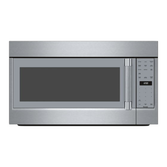
- Page 1 Installation G U I D E Professional Series Handle Microwave Oven MU30WSU T H E R M A D O R . C O M...
-
Page 3: Table Of Contents
Adapting microwave blower ......... 12 Preparing cabinet ............13 Mounting the microwave oven ........13 Hood exhaust ..............14 Testing Operation ............. 16 THERMADOR® Support ........... 16 Before Calling Service ........... 16 Data Plate ..............16 Service ................16 Parts and Accessories ........... 16... -
Page 4: Safety Definitions
Safety Definitions S a f e t y D e f i n i t i o n s WARNING This indicates that death or serious injuries may occur as a result of non-observance of this warning. CAUTION This indicates that minor or moderate injuries may occur as a result of non-observance of this warning. -
Page 5: Important Safety Instructions
IMPORTANT SAFETY INSTRUCTIONS READ AND SAVE THESE INSTRUCTIONS INSTALLER: LEAVE THESE INSTRUCTIONS WITH THE Electric Safety I M P O R T A N T S A F E T Y I N S T R U C T I O N S R E A D A N D S A V E T H E S E... -
Page 6: Related Equipment Safety
IMPORTANT SAFETY INSTRUCTIONS READ AND SAVE THESE INSTRUCTIONS GROUNDING INSTRUCTIONS This appliance must be grounded. Grounding reduces the risk of electric shock by providing a safe pathway for electric current in the event of a short circuit. This appliance is equipped with a cord having a grounding wire with a grounding plug. -
Page 7: Checklist For Installation
Checklist for Installation Find wall studs. Section: Install Appliance - Finding the wall studs Attach the mounting plate to the wall. Section: Install Appliance - Attaching the mounting plate to the wall Use this checklist to verify that you have completed each Adapt the microwave blower. -
Page 8: Parts Included
Location requirements Optional tools Carpenter square ▯ Installation dimensions Tin snips (to cut damper) ▯ Scissors (to cut cabinet template) ▯ Filler blocks or scrap wood pieces (for recessed ▯ bottom cabinet installations) Parts included You will find the installation hardware contained in packet with the unit. -
Page 9: Power Requirements
Note: Take into account that the front and rear Appliance dimensions measurements of the appliance are not identical. Power Requirements The outlet must be properly grounded in accordance with all applicable codes. It can be installed anywhere inside the cabinet above the appliance, within reach of the power cord (approx. -
Page 10: Install Appliance
Install Appliance Removing the mounting plate No wall studs at corner holes Note: To avoid possible damage to the work surface or to the bottom of the appliance, cover the work surface. Remove any remaining contents from the microwave oven cavity. Remove the screws from the mounting plate. -
Page 11: Attaching The Mounting Plate To The Wall
Attaching the mounting plate to the wall Attach toggle wings from the back of the mounting plate onto each bolt. Leave enough space for toggle wings to go through the wall and to open. Preparing rear wall CAUTION Wear gloves to avoid cutting fingers on sharp edges. -
Page 12: Adapting Microwave Blower
Adapting microwave blower This microwave is shipped assembled for Room Venting Installation. The blower unit is already in place and must not to be adapted. Adapting microwave blower for roof venting Remove and save the screws holding the blower motor and the blower plate. Lift up the blower plate and put it aside. -
Page 13: Preparing Cabinet
Mounting the microwave oven Replace the blower plate and secure with the screws removed in Step 1. Notes If the bottom of the upper cabinet is recessed or has ▯ front overhang, you will need to prepare 2" x 2" (51 mm x 51 mm - depth equivalent to cabinet recess or overhang) filler blocks to provide additional support for the bolts:... -
Page 14: Hood Exhaust
Insert the two remaining self-aligning screws through outer top cabinet holes. Turn two full turns on each screw. Hood exhaust When venting exhaust to the outside, hood exhaust ducts will be required. Read the following carefully. Note: It is important that venting be installed using the most direct route and with as few elbows as possible. - Page 15 Duct Pieces Number used Equivalent Length 90° Elbow 10 ft (3 m) 45° Elbow 5 ft (1.5 m) 90° Elbow 25 ft (7.6 m) 45° Elbow 5 ft (1.5 m) Roof Cap 24 ft (7.3 m) Straight Duct 6" (152 mm Round or 3 1/4"...
-
Page 16: Testing Operation
The data plate can be found on the inside of the 800-735-4328 appliance. www.thermador.ca Parts and Accessories Parts, filters, descalers, stainless steel cleaners and more can be purchased in the THERMADOR® eShop or by phone. http://store.thermador.com/us Canada If you live in any of the Atlantic provinces, Ontario, or ▯... - Page 17 Preparación del gabinete ..........27 Montaje del horno microondas ........28 Escape de la campana ..........29 Prueba del funcionamiento ........30 Soporte técnico de THERMADOR® ......31 Antes de llamar al servicio ........... 31 Placa de datos ............... 31 Servicio técnico ............. 31...
-
Page 18: Definiciones De Seguridad
Definiciones de seguridad D e f i n i c i o n e s d e s e g u r i d a d ADVERTENCIA Esto indica que pueden producirse heridas graves o incluso la muerte si no se cumple con esta advertencia. -
Page 19: Instrucciones De Seguridad Importantes
INSTRUCCIONES DE SEGURIDAD IMPORTANTES LEA Y CONSERVE ESTAS INSTRUCCIONES INSTALADOR: DEJE ESTAS INSTRUCCIONES CON EL Es responsabilidad del propietario y del instalador I N S T R U C C I O N E S S E G U R I D A D I M P O R T A N T E S L E A C O N S E R V E E S T A S... -
Page 20: Seguridad Del Equipo Relacionado
INSTRUCCIONES DE SEGURIDAD IMPORTANTES LEA Y CONSERVE ESTAS INSTRUCCIONES alineación, la integridad y la conexión de la cavidad ADVERTENCIA sean correctas. Se deben reparar, reemplazar o ajustar todos los No utilice los quemadores de la cubierta de gas sin ▯ componentes dañados o mal ajustados de los colocar las ollas en su sitio. -
Page 21: Lista De Verificación De Instalación
Lista de verificación de instalación Busque los pasadores de pared. Sección: Montaje del electrodoméstico - Búsqueda de los pasadores de pared Acople la placa de fijación a la pared. Sección: Montaje del electrodoméstico - Acoplamiento de la placa de fijación a la pared Use esta lista de verificación para verificar que haya completado cada paso del proceso de instalación. -
Page 22: Herramientas Y Piezas Necesarias
Herramientas y piezas necesarias Piezas incluidas Destornillador con cabeza Phillips ▯ Lápiz. ▯ Regla o cinta métrica, y borde recto. ▯ Taladro. ▯ Brocas: 3/16 pulg., 1/2 pulg., 5/8 pulg. ▯ Guantes. ▯ Sierra (de vaivén, de perforación o de punta). ▯... -
Page 23: Requisitos De Ubicación
Requisitos de ubicación Medidas del aparato Medidas para la instalación Nota: Tome en cuenta que las mediciones delantera y trasera del aparato no son idénticos. Requisitos de electricidad La toma de corriente debe tener la conexión a tierra adecuada de conformidad con todos los códigos correspondientes. -
Page 24: Instalación Eléctrica
Instalación eléctrica El modelo mencionado en la tapa frontal está diseñado tamaño del cable debe cumplir con los requisitos del para conectarse a una fuente de alimentación de 120 V Código Eléctrico Nacional o del código local vigente CA y 60 Hz. Se utiliza un conector NEMA 5-15 para para esta especificación. -
Page 25: Acoplamiento De La Placa De Fijación A La Pared
Acoplamiento de la placa de fijación a la Sin pasadores de pared en los orificios de las esquinas pared Preparación de la pared trasera ATENCION Utilice guantes para evitar cortarse los dedos en bordes filosos. Nota: Asegúrese de que la parte inferior del gabinete esté... -
Page 26: Adaptación Del Ventilador Del Microondas
Verifique que la placa esté centrada en forma Acoplamiento de la placa de fijación adecuada; asegúrese de que esté nivelada. Retire las alas de anclaje de los pernos. Ajuste firmemente todos los tornillos, incluido el Inserte los pernos en la placa de fijación a través de tornillo para madera. -
Page 27: Preparación Del Gabinete
Acople el adaptador del escape a la parte superior de ATENCION la placa del ventilador deslizándolo en las guías. Empújelo hacia adentro en forma segura hasta que se No tire del cableado de la unidad del ventilador encuentre en los fijadores. Asegúrese de que la ni lo estire. -
Page 28: Montaje Del Horno Microondas
Corte el orificio de 2 pulg. (51 mm) en “D”. Este orificio es para el cable de alimentación eléctrica. Nota: Si el gabinete es de metal, utilice el pasacables de nailon alrededor de la abertura para proteger el cable. Únicamente para la instalación de ventilación de techo: Corte la sección sombreada “E”... -
Page 29: Escape De La Campana
Escape de la campana Para instalar el filtro de ventilación, introducir las dos clavijas de la parte trasera del filtro en las ranuras Para ventilar aire de escape al exterior, se requieren situadas en la parte trasera de la abertura del mismo. conductos de escape de la campana. -
Page 30: Prueba Del Funcionamiento
Piezas de conductos Cantidad utilizada Longitud equivalente Codo de 45° 5 pies (1.5 m) Codo de 90° 25 pies (7.6 m) Codo de 45° 5 pies (1.5 m) Tapa de techo 24 pies (7.3 m) Conducto recto redondo de 6 pulg. (152 mm) o rectan- 1 pie (0.3 m) gular de 3 1/4 pulg. -
Page 31: Soporte Técnico De Thermador
La placa de datos puede encontrarse en el interior del aparato. Piezas y accesorios Puede comprar piezas, filtros, productos para eliminar el sarro, limpiadores para acero inoxidable y más artículos en la tienda electrónica de THERMADOR® o por teléfono. EE. UU. http://store.thermador.com/us Canadá... - Page 36 1 9 0 1 M A I N S T R E E T , S U I T E 6 0 0 I R V I N E , C A 9 2 6 1 4 / / 1 - 8 0 0 - 7 3 5 - 4 3 2 8 / / W W W . T H E R M A D O R . C O M ©...
Need help?
Do you have a question about the Professional Series and is the answer not in the manual?
Questions and answers