Table of Contents
Advertisement
Advertisement
Table of Contents

Related Manuals for Nidec Leroy-Somer R180


Summary of Contents for Nidec Leroy-Somer R180
- Page 1 R180 Installation and maintenance...
- Page 2 Installation and maintenance Electric Power Generation 5599 en - 2019.10 / e R180 This manual concerns the alternator AVR which you have just purchased. We wish to draw your attention to the contents of this maintenance manual. SAFETY MEASURES Before using your machine for the first time, it is important to read the whole of this All servicing or repair operations perfor- installation and maintenance manual.
-
Page 3: Table Of Contents
Installation and maintenance Electric Power Generation 5599 en - 2019.10 / e R180 CONTENTS 1 - GENERAL DESCRIPTION ....................4 2 - AVR PARAMETERS ......................5 3 - TECHNICAL SPECIFICATION ...................6 4 - MAIN FUNCTION OF THE AVR ..................7 4.1 - Connection diagram for low voltage range ..............7 4.2 - Connection diagram for high voltage range with droop powered by AREP .....8 4.3 - Connection diagram for high voltage range with droop powered by PMG ......9 5 - AVR SETTINGS ........................ -
Page 4: General Description
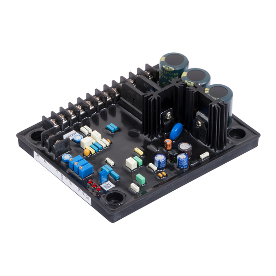
Installation and maintenance Electric Power Generation 5599 en - 2019.10 / e R180 1 - GENERAL DESCRIPTION The R180 is triggered from the alternator remanent voltage. The R180 is a fully solid- state automatic voltage regulator (AVR) which is used for excitation of a brushless alternator powered by a Permanent- Magnet (PMG) exciter or by auxiliary windings. -
Page 5: Avr Parameters
Installation and maintenance Electric Power Generation 5599 en - 2019.10 / e R180 2 - AVR PARAMETERS potentiometer sets the maximum voltage range for the external potentiometer or the UFRO selection link auxiliary input range. Open - 60 Hz operating mode. Closed - 50 Hz operating mode. -
Page 6: Technical Specification
Installation and maintenance Electric Power Generation 5599 en - 2019.10 / e R180 3 - TECHNICAL SPECIFICATION Sensing input 3-ph/2-ph - 220/230/240/380/400/415 volts for 50 Hz 3-ph/2-ph - 208/240/277/380/416/440/480 Volts for 60 Hz Voltage range High 300 V to 530 V Voltage range Low 180 V to 310 V Droop... -
Page 7: Main Function Of The Avr
Installation and maintenance Electric Power Generation 5599 en - 2019.10 / e R180 4 - MAIN FUNCTION OF THE AVR 4.1 - Connection diagram for low voltage range... -
Page 8: Connection Diagram For High Voltage Range With Droop Powered By Arep
Installation and maintenance Electric Power Generation 5599 en - 2019.10 / e R180 4.2 - Connection diagram for high voltage range with droop powered by AREP... -
Page 9: Connection Diagram For High Voltage Range With Droop Powered By Pmg
Installation and maintenance Electric Power Generation 5599 en - 2019.10 / e R180 4.3 - Connection diagram for high voltage range with droop powered by PMG... -
Page 10: Avr Settings
Installation and maintenance Electric Power Generation 5599 en - 2019.10 / e R180 5 - AVR SETTINGS - If oscillations are not seen on voltage build-up, turn the “STABILITY” trimmer anticlockwise till oscillations appear and then slightly turn it clockwise to remove any oscillation. -
Page 11: Troubleshooting Chart
Installation and maintenance Electric Power Generation 5599 en - 2019.10 / e R180 6 - TROUBLESHOOTING CHART Symptom Cause Action No voltage Fuse links blown Change the fuse links. build-up Low residual voltage across Run alternator at correct rpm. If the problem X1 and X2 terminals persists, disconnect the AVR and connect a 24 VDC battery between F1 and F2. -
Page 12: Multimeter Test
Installation and maintenance Electric Power Generation 5599 en - 2019.10 / e R180 7 - MULTIMETER TEST Connect the black lead to Z2. The multimeter will display 0.4 V to 0.6 V WARNING If the multimeter displays 0 V or OL in diode test, the bridge rectifier diodes are faulty. -
Page 13: Static Test Procedure
Installation and maintenance Electric Power Generation 5599 en - 2019.10 / e R180 8 - STATIC TEST PROCEDURE 8.2 - Connection - Connect the 100 W bulb between the F1 8.1 - Test equipment and F2 terminals on the AVR - 3-phase variac - Connect the 110 V transformer output to - AC/DC voltmeter... -
Page 14: Test Procedure
Installation and maintenance Electric Power Generation 5599 en - 2019.10 / e R180 8.3 - Test procedure LED will light up and the bulb will be ON for 5 sec and then switch OFF. 1. Build-up test 6. Stability test To test build-up, start the variac at 0 volts The bulb dimming rate during the voltage and set the output voltage to around 5 VAC... -
Page 15: Dimensions
Installation and maintenance Electric Power Generation 5599 en - 2019.10 / e R180 9 - DIMENSIONS TOP VIEW SIDE VIEW... -
Page 16: Spare Parts
Installation and maintenance Electric Power Generation 5599 en - 2019.10 / e R180 10 - SPARE PARTS 10.1 - Designation Description Type Code R180 5089747 10.2 - Technical support service Our technical support service will be pleased provide additional information you may require. For all spare parts orders or technical support requests, send your request to service.epg@leroy-somer.com or your... -
Page 17: Disposal And Recycling Instructions
Installation and maintenance Electric Power Generation 5599 en - 2019.10 / e R180 Disposal and recycling instructions committed limiting environmental impact of our activity. We continuously monitor production processes, material sourcing and products design to improve recyclability and minimise our environmental footprint. These instructions are for information purposes only. - Page 18 Installation and maintenance Electric Power Generation 5599 en - 2019.10 / e R180...
- Page 19 Service & Support Our worldwide service network of over 80 facilities is at your service. This local presence is our guarantee for fast and efficient repair, support and maintenance services. Trust your alternator maintenance and support to electric power generation experts. Our field personnel are 100% qualified and fully trained to operate in all environments and on all machine types.
- Page 20 Linkedin.com/company/leroy-somer Twitter.com/Leroy_Somer_en Facebook.com/LeroySomer.Nidec.en YouTube.com/LeroySomerOfficiel 5599 en - 2019.10 / e...
Need help?
Do you have a question about the Leroy-Somer R180 and is the answer not in the manual?
Questions and answers