Table of Contents
Advertisement
L4278
Rev. B
To protect your warranty, use only ENERPAC hydraulic oil.
Models:
• EP3204JB
• EP3204JI
• EP3204JE
For use with single-acting
hydraulic cylinders and tools.
Control Valve
A B
Control Valve
Control Valve
Control Valve
A B
A B
A B
T
P
T
P
T
P
T
P
07/19
Models:
Control Valve
• EP3404JB
• EP3404JI
• EP3404JE
For use with double-acting
hydraulic cylinders and tools.
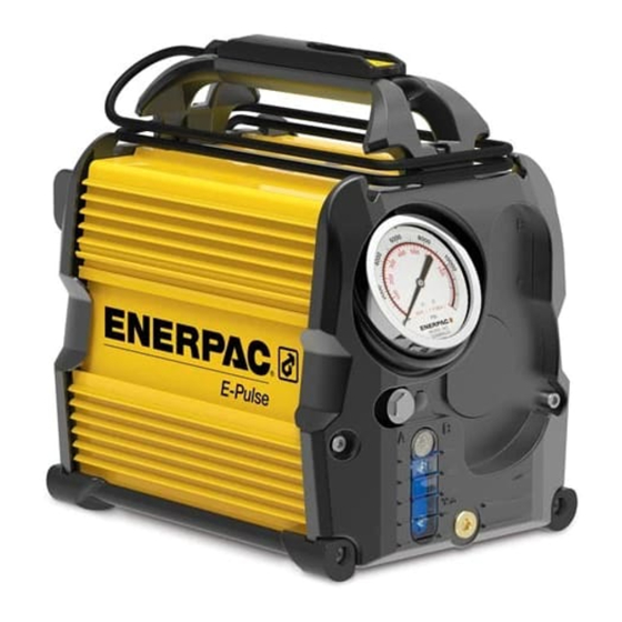
Instruction Sheet
E-Series
Electric Manual Valve Pumps
T
T
Control Valve
A
A
A
A
T
P
P
T
P
P
Advertisement
Table of Contents

Related Manuals for Enerpac E-Pulse EP3204JB


Summary of Contents for Enerpac E-Pulse EP3204JB
- Page 1 Instruction Sheet E-Series Electric Manual Valve Pumps L4278 Rev. B 07/19 To protect your warranty, use only ENERPAC hydraulic oil. Control Valve Models: • EP3204JB • EP3204JI • EP3204JE For use with single-acting hydraulic cylinders and tools. Control Valve Models:...
-
Page 2: Table Of Contents
Table of Contents: 1.0 SAFETY .............3 6.3 Pendant ..........10 1.1 Important Safety Instructions ....3 6.4 Variable Speed Control ......11 1.2 General Hydraulic Safety Precautions ..3 6.5 Constant Speed and Constant Power Modes ............11 1.3 Electrical Safety ........4 6.6 3-Way, 2-Position Control Valve 1.4 Additional Precautions ......5 (EP3204J Models) .........11 1.5 IP Ratings... -
Page 3: Safety
Off-center loads produce considerable strain If training is needed, contact your local Enerpac distributor or on cylinders and plungers. In addition, the load may slip or fall. -
Page 4: Electrical Safety
Return the pump to the nearest Enerpac electrician. After the reconnection, the pump should comply authorized service center for examination, repair, or electrical with all local codes and ordinances. -
Page 5: Additional Precautions
Outdoor Appliances.” affixed to the pump. If worn or missing, obtain replacements from 1.4 Additional Precautions Enerpac. Refer to Figure 1 for locations WARNING Do not use electric pumps in an explosive atmosphere. Sparks and electrical arcing could ignite combustible vapors or airborne dust CAUTION Check electrical power requirements on pump data plate. -
Page 6: Product Data
Oil Type Description Connections Number gal. 3-way, 2-position Single-acting hydraulic EP3204J_ 3/8" NPTF 39.4 17.9 Enerpac HF (Advance / Release) cylinders or tools 4-way, 3-position, Tandem Center Double-acting hydraulic EP3404J_ 3/8" NPTF 40.0 18.1 Enerpac HF (Advance / Neutral / Retract) cylinders or tools Approximate weight of pump including oil. -
Page 7: Pump Performance Curves
2.3 Pump Performance Curves Models EP3204JB and EP3404JB (IMPERIAL) (METRIC) 120V FLOW . PRESSURE 120V FLOW . PRESSURE 2000 2000 4000 4000 6000 6000 8000 8000 10,000 10,000 Pressure (bar) ▶ Pressure (psi) ▶ 100% of rated output 100% of rated output 50% of rated output 50% of rated output 25% of rated output... -
Page 8: Major Features And Components
3.0 MAJOR FEATURES AND COMPONENTS EP3204J Models EP3404J Models Key: 1. Pendant and Cable 2. Carrying Handle and Pendant Cable Storage 3. Directional Control Valve 3-Way, 2-Position 4. Directional Control Valve, 4-Way, 3-Position 5. Hyd. Reservoir Air Breather and Filter 6. -
Page 9: Product Description
4.0 PRODUCT DESCRIPTION 4.1 Introduction The Enerpac E-Series electric manual valve pumps are designed for use with industrial hydraulic cylinders and tools rated at 10,000 psi [700 bar] working pressure. Features include: • Manual 3-way, 2-position control valve (EP3204J Models) or manual 4-way, 3-position control valve with tandem center (EP3404J Models). -
Page 10: Hydraulic Reservoir
For most shipping destinations, the hydraulic reservoir is pre- reposition the pump by dragging it by the hydraulic hose(s), AC filled at the factory with Enerpac HF hydraulic oil. power cord or pendant cable. However, as a precaution, always check the oil level before 6.2 Ventilation System... -
Page 11: Variable Speed Control
6.5 Constant Speed and Constant Power Modes WARNING Continuously monitor the load and be • When the speed control knob is set between the full counter- prepared to stop the pump immediately. Never allow the clockwise (25%) and midpoint (50%) positions, the pump pump to operate in the latched mode while it is unattended. -
Page 12: 4-Way, 3-Position Control Valve (Ep3404J Models)
working under the load. Refer to additional information and WARNING The pump contains no safety locking valve precautions in Section 7.7 of this manual. and is NOT designed to provide support while persons are working under the load. Refer to additional information and 7.0 OPERATION precautions in Section 7.7 of this manual. -
Page 13: Air Removal
• Additional flow control devices (optional accessories - refer to run the cylinder or tool through several complete advance-retract Enerpac catalog) may be required to more precisely control cycles before placing the pump into service. Do this with no load the rate of retraction. -
Page 14: Supporting The Load
“A” and “B” ports. position as mechanical load support devices are being installed or removed. Refer to the Enerpac catalog for Install a 0-15,000 psi [0-1035 bar] hydraulic pressure gauge in additional information. -
Page 15: Hydraulic System Maintenance
An internal check valve will prevent the pressure from dropping if the set screw is turned counter-clockwise while the • Use of oils other than Enerpac HF may result in damage control valve lever is in the “A” position. To lower the pressure, to pump hydraulic components and will void the Enerpac follow steps 12a through 12e. -
Page 16: Adding Oil
Funnel (user-supplied) OVERFILLED 1/4" - 1/2" Dia. FULL [6.3- 12.7 mm] Drain/Fill Plug FILL POSITION ADD OIL (See Figures 13 & 14) Figure 12, Oil Level Indicator Drain/Fill Port 10.3 Adding Oil Be sure that hydraulic cylinder or tool is fully retracted. Be certain that pump is off and that all hydraulic pressure is fully relieved. -
Page 17: Pump Priming/Air Purging
RESERVOIR AIR BREATHER (Up to bottom of air breather) FULL FULL (Up to bottom of air breather) ADD 0.5 QUARTS ADD 0.47 LITERS ADD 1.0 QUARTS ADD 0.95 LITERS ADD 1.5 QUARTS ADD 1.42 LITERS ADD 2.0 QUARTS ADD 1.89 LITERS ADD 2.5 QUARTS ADD 2.37 LITERS EMPTY - ADD 3.0 QUARTS... -
Page 18: Cleaning And Inspection
• Remove any dust or dirt from the pump front and rear covers For repair service, contact your nearest Enerpac Authorized and the pump top and bottom surfaces. Be sure that all four air Service Center. - Page 19 Table 1 - Troubleshooting Guide (continued) Problem Possible Cause Action 3. Pump fails to build h. Pump internal leakage. Contact Enerpac Authorized Service Center. pressure or builds Pump seals worn or damaged. Contact Enerpac Authorized Service Center. less than full pressure (continued).
- Page 20 AC power cord is being plugged into the electrical outlet. The pendant LED indicator should appear solid green approximately 3 seconds after power has been reconnected. This indicates that the pump is in normal operational mode. b. Pump electrical and/or mechanical Contact Enerpac Authorized Service Center. problems.
-
Page 21: Pump Fault Codes (User-Level)
BUTTON FAULT 1 red blink followed by a • If problem persists, contact 1 second pause. Sequence Enerpac Authorized Service repeats until problem is Center. corrected. Check pendant and pendant cable for obvious signs of damage or wear. - Page 22 Notes:...
- Page 23 Notes:...
- Page 24 http://www.enerpac.com...
Need help?
Do you have a question about the E-Pulse EP3204JB and is the answer not in the manual?
Questions and answers