Table of Contents
Advertisement
Quick Links
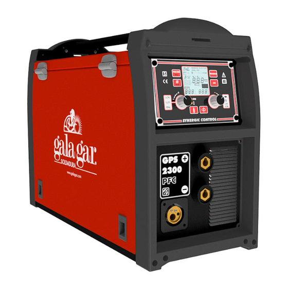
GPS 2300 PFC BI-PULSE
TECHNICAL INSTRUCTIONS MANUAL.
EN
MULTIPROCESS INVERTER. SYNERGIC EQUIPMENT FOR MIG/MAG WELDING
GPS 2300 PFC BI-PULSE
Ref.: 532.00.100
(230V - 50/60Hz)
THIS EQUIPMENT SHOULD BE USED ONLY BY PROFESSIONALS.
FOR THE BENEFIT OF YOUR WORK, PLEASE READ THIS MANUAL
EN
CAREFULLY.
Jaime Ferrán 19 50014 ZARAGOZA (Spain)
Tel.:.00 34 976473410 - Fax: 00 34 976472450
Ref.: 532.17.147 / v0
Advertisement
Table of Contents

Related Manuals for GALAGAR GPS 2300 PFC BI-PULSE


Summary of Contents for GALAGAR GPS 2300 PFC BI-PULSE
- Page 1 GPS 2300 PFC BI-PULSE TECHNICAL INSTRUCTIONS MANUAL. MULTIPROCESS INVERTER. SYNERGIC EQUIPMENT FOR MIG/MAG WELDING GPS 2300 PFC BI-PULSE Ref.: 532.00.100 (230V - 50/60Hz) THIS EQUIPMENT SHOULD BE USED ONLY BY PROFESSIONALS. FOR THE BENEFIT OF YOUR WORK, PLEASE READ THIS MANUAL CAREFULLY.
-
Page 2: Table Of Contents
GPS 2300 PFC BI-PULSE EN CONTENTS 1. GENERAL DESCRIPTION. TECHNICAL FEATURES 3 1.1. STANDAR ACCESORRIES INCLUDED --------------------------------------------------------------------------------------------------- 4 1.2. RECOMMENDED ACCESSORIES -------------------------------------------------------------------------------------------------------- 4 1.3. USING MODES ---------------------------------------------------------------------------------------------------------------------------- 4 1.4. WELDING PROGRAMS WITH PULSED ARC 5 1.5. WELDING PROGRAMS WITH STANDARD ARC 5 2. -
Page 3: General Description. Technical Features
For MIG/MAG and TIG procedures, this equipment is able to memorise up to 10 groups of welding parameters (JOBS), offering more than 25 welding programs. GPS 2300 PFC BI-PULSE Technical Features. Data according to standard EN60974-1 GPS 2300 PFC BI-PULSE TECHNICAL FEATURES Ref. -
Page 4: Standar Accesorries Included
GPS 2300 PFC BI-PULSE 1.1. STANDAR ACCESORRIES INCLUDED WITH EQUIPMENT Ref. 53200100. REFERENCE DESCRIPTION 532.17.147 Instructions Manual GPS 2300 PFC BI-PULSE 532.17.087 Syner Bi-Pulsed Control Panel quick guide 532.12.129 Input cable 3x2.5 mm , 3 m (with Schuko plug incl.) 423.12.030 Machine-gas connection (2 m) / coupling... -
Page 5: Welding Programs With Pulsed Arc
GPS 2300 PFC BI-PULSE 1.4. WELDING PROGRAMS WITH PULSED ARC. Display Wire display Base Material Filler material Shielding gas Gas display material display SG2 SG3 0.030 ER 70 S 6 Ar + CO2 (20%) Ar CO2 SG2 SG3 0.035 SG II - SG III... -
Page 6: Transport And Installation
GPS 2300 PFC BI-PULSE 2. TRANSPORT AND INSTALLATION. 2.1. TRANSPORT AND PACKAGING Knocks and sudden movements must be avoided when transporting the equipment. In any case, the packaging must be protected from water. HANDLE THE EQUIPMENT CAREFULLY, IT WILL LAST LONGER ! 2.2. -
Page 7: Start-Up. Operation And Adjustments
GPS 2300 PFC BI-PULSE 3. START-UP. OPERATION AND ADJUSTMENT CONTROLS. 3.1. OPERATION CONTROLS. Controls and displays of synergic control. Euro-connector. MIG and TIG welding torches connection. Negative pole. Positive pole. Gas inlet hose. Power supply cable. Master switch Adjustment lever of wire driving ON / OFF pressure. -
Page 8: Front Control Panel
GPS 2300 PFC BI-PULSE 3.2. FRONT CONTROL PANEL. LED INDICATORS Green LED indicator of start-up. Amber LED indicator of equipment shutdown due thermal overload or input voltage conditions outside margin. BUTTONS OF DIGITAL CONTROL PANEL Welding process selection. Momentary pressure. -
Page 9: Welding Processes
GPS 2300 PFC BI-PULSE ADJUSTMENT ENCODERS OF DIGITAL CONTROL PANEL MIG WELDING MODE, MANUAL PROGRAM . Welding voltage control. U U . The control can be carried out during the welding process. 2min 2max MIG WELDING MODE, SYNERGIC PROGRAM . -
Page 10: Mig/Mag Welding Installation, Start-Up And Operation Systems
GPS 2300 PFC BI-PULSE 3.4. MIG/MAG WELDING INSTALLATION, START-UP AND OPERATION SYSTEMS. PULSE PULSE PULSE SPOT PULSE BI-PULSE SPOT PULSE Maximum time in wire approach process without generating an electric arc. (5s - Tacer: Not adjustable value). Maximum arc interruption time During that time the arc can be re-established. (4s - Tci: Not adjustable value). - Page 11 GPS 2300 PFC BI-PULSE 3.4.1.1. INSTALLATION OF STANDARD MIG/MAG SYSTEM. TORCH TO POSITIVE POLE. Recommended installation for Fe welding (Standard Steel) MARK REF. DESCRIPTION REMARKS INCLUDED Input cable 3x2.5 mm , 3 m ( with Schuko plug incl.) INCLUDED Wire reel Ø37, 0.8-1.0 mm “V”...
- Page 12 GPS 2300 PFC BI-PULSE 3.4.1.3. INSTALLATION OF MIG/MAG SYSTEM WITHOUT GAS (FCAW). TORCH TO NEGATIVE POLE. Recommended installation for welding “without gas” (FCAW) MARK Ref. DESCRIPTION REMARKS Input cable 3x2.5 mm2, 3 m (with plug incl.). INCLUDED INCLUDED Wire reel Ø37, 0.8-1.0 mm “V”...
- Page 13 GPS 2300 PFC BI-PULSE 13th) Bleed gas by means of the P5 push-button, checking that the flow is between 8 and 14 l/min. Bled the wire P5: GAS BLEEDING P6: WIRE BLEEDING Gas bleeding. The gas solenoid valve is activated The drive motor is whilst depressed.
- Page 14 GPS 2300 PFC BI-PULSE 3.4.3.3. ADJUSTMENT SYSTEM FOR PULSED – BIPULSED MIG/MAG WELDING. SYNERGIC PROGRAM. 8-digit display Wire display Material Gas display display Standard Al Mg Mg 5% Cu Si Si 3% 0.035 Prog. No. Description 8-digit display Wire display...
- Page 15 GPS 2300 PFC BI-PULSE 3.4.3.3.1. BI-PULSE PROGRAM INDICATIONS ON DISPLAY INTERMITTENT INTERMITTENT PROGRAM No. = 4S-SPECIAL SPECIAL Bi-PULSE PULSE PULSE PULSE 1.0 mm 1.0 mm 1.0 mm Bi-PULSE WIRE TYPE WELDING WELDING VOLTAGE INTENSITY 3.4.4. PARAMETERS SETTING MODE. MIG/MAG PROCESSES.
- Page 16 GPS 2300 PFC BI-PULSE 3.4.4.3. CYCLE PARAMETERS. MIG PROCESS (CONTINUOUS) MIG PROCESS OPERATING CYCLES 2S/4S MOD (2/4 STROKES) I2>0 tacer Torch 1T 2T 3T 4T 2T 1T 2S-S/4S-S MOD (2/4 STROKES-SPECIAL) CYCLE PARAMETERS FOR STANDARD MIG WELDING MODE IN CONTINUOUS CYCLE...
- Page 17 GPS 2300 PFC BI-PULSE 3.4.4.4. CYCLE PARAMETERS. MIG SPOT WELDING PROCESS. MIG SPOT PROCESS OPERATING CYCLES MOD 2S; TOF OFF MOD 2S-S; TOF OFF I2>0 I2>0 IS-VhS tacer tacer TBB TPS Torch Torch 1T 2T 2T 1T MOD 2S; TOF ON MOD 4S;...
- Page 18 GPS 2300 PFC BI-PULSE 3.4.4.5. CYCLE PARAMETERS. PULSED MIG PROCESS (CONTINUOUS) CYCLE PARAMETERS FOR PULSE MIG WELDING MODE IN CONTINUOUS CYCLE 2S/4S MOD (2/4 STROKES) I2>0 tacer Torch 1T 2T 3T 4T 2T 1T 2S-S/4S-S MODE (2/4 STROKES-SPECIAL) CONFIGURABLE Parameter...
- Page 19 GPS 2300 PFC BI-PULSE 3.4.4.6. CYCLE PARAMETERS. BI-PULSED MIG PROCESS (CONTINUOUS) OPERATION CYCLES OF BI-PULSED MIG PROCESS 2S/4S MOD (2/4 STROKES) I2>0 1/FBP I2>0 tacer Torch 1T 2T 3T 4T 1T 2T 2S/4S MOD (2/4 STROKES)
- Page 20 GPS 2300 PFC BI-PULSE CYCLE PARAMETERS FOR Bi-PULSED MIG WELDING MODE IN CONTINUOUS CYCLE CONFIGURABLE Parameter PARAMETER DESCRIPTION FACTORY VALUE VALUE Drop detachment force correction. -10 ÷ 10 (20 positions) Arc length correction in upper working point of dual pulsed -30%÷...
- Page 21 GPS 2300 PFC BI-PULSE 3.4.4.7. CYCLE PARAMETERS. PULSED MIG SPOT WELDING PROCESS. OPERATING CYCLES OF PULSED MIG SPOT WELDING PROCESS MOD 2T ; TOF OFF MOD 2TS (2 TIEMPOS ESPECIAL) ; TOF=OFF I2>0 I2>0 IS-VhS tacer tacer TBB TPS Torch Torch 2T...
-
Page 22: Tig Welding. Installation, Start-Up And Operation Controls
GPS 2300 PFC BI-PULSE 3.5. TIG WELDING. INSTALLATION, START-UP AND OPERATING CONTROLS. Depending on whether the installation is cooled or not, we must set the equipment during the first start-up. AUTOMATIC COOLING: Working mode with cooled torch. The cooling only works in welding mode and will switch off automatically 2 minutes after carrying out the welding process. - Page 23 GPS 2300 PFC BI-PULSE 3.5.1. TIG SYSTEM INSTALLATION. TORCH TO NEGATIVE POLE. MARK Ref. DESCRIPTION REMARKS Input cable 3x2.5 mm , 3 m (with INCLUDED Schuko plug incl.) INCLUDED Machine-gas connection INCLUDED Earth clamp cable 376.00.000 Argon pressure regulator – Mod. EN 2...
- Page 24 GPS 2300 PFC BI-PULSE 3.5.3. COOLED TIG SYSTEM INSTALLATION. TORCH TO NEGATIVE POLE. MARK REF. DESCRIPTION REMARKS Input cable 3x2.5 mm , 3 m (with Schuko plug INCLUDED incl.) INCLUDED Machine-gas connection INCLUDED Earth clamp cable INCLUDED WCS-510 INCLUDED Connection extension from WCS-510 to torch.
- Page 25 GPS 2300 PFC BI-PULSE 3.5.5. ADJUSTMENT SYSTEM FOR CONVENTIONAL DC TIG WELDING MODE. E2: ADJUST WELDING P1: SELECT PROCESS CURRENT I D3 : Note: Selection of 2S/4S is carried out in parameter setting mode. 3.5.6. ADJUSTMENT SYSTEM FOR PULSED TIG WELDING MODE.
- Page 26 GPS 2300 PFC BI-PULSE 3.5.8. CYCLE PARAMETERS. TIG PROCESS. TIG PROCESS OPERATING CYCLES MOD 4T MOD 2T Torch Torch 1T 2T 3T 4T 1T CYCLE PARAMETERS – TIG PROCESS Parameter Parameter description CONFIGURABLE VALUE...
-
Page 27: Mma Welding. Installation, Start-Up And Operation Controls
GPS 2300 PFC BI-PULSE 3.6. MMA WELDING. INSTALLATION, START-UP AND OPERATING CONTROLS. 3.6.1. MMA SYSTEM INSTALLATION. ELECTRODE-HOLDER CLAMP TO POSITIVE POLE. Note: Electrode-holder clamp polarity depend on the electrode (consult the characteristics provided by the manufacturer) MARK REF. DESCRIPTION REMARKS INCLUDED 3x2.5 mm2, 3 m (with Schuko plug... - Page 28 GPS 2300 PFC BI-PULSE 3.6.4.1. ADJUSTMENT SYSTEM FOR MMA / MMA CEL SETTING PARAMETERS. P1: ENTER/EXIT TO E1: SELECT CYCLE P1: SELECT PROCESS PARAMETERS SETTING E2: ADJUST VALUE P1: SAVE PARAMETERS PARAMETER MODE D2 : D3 : SAVED SETTING PARAMETERS PARAMETERS 3.6.4.2.
-
Page 29: Job Recording Mode
GPS 2300 PFC BI-PULSE 3.7. JOB RECORDING MODE. 3.7.1. PROCESSES WITH JOB RECORDING MODE. RECORDED VARIABLES. Program Variables of recording Vh (m/min); U (V); L/D; MOD; TPR; Tc; IS; TS; CCE; DWS1; DWS2; IE; TE; TPS; FDC; MANUAL TBB; DIM Thickness synergic line e(mm);... -
Page 30: Timer Mode. Process Statistics
GPS 2300 PFC BI-PULSE 3.8. TIMER MODE. PROCESS STATISTICS. 3.8.1. ENTER/EXIT OPERATION. TIMER MODE The indication appears after keeping pressed for 1 s. The Select the process: indication is maintained whilst Wait for 2 seconds without MIG/MMA/TIG. depressed. pressing. When it reaches 999 minutes it changes into hours, and the minutes indication will disappear. -
Page 31: Hold Mode
GPS 2300 PFC BI-PULSE 3.9. HOLD MODE. At the end of the welding process the welding parameters are automatically memorised. This will be indicated on the LCD screen with the word "HOLD". D2- It will indicate the last average value of stored welding voltage. -
Page 32: Maintenance Operations. Recommendations
GPS 2300 PFC BI-PULSE 4. MAINTENANCE OPERATIONS. RECOMMENDATIONS. In order for the equipment to have a long life we must KEEP THE WELDING TORCH IN GOOD follow some essential rules for maintenance and use. CONDITIONS FOR USE. Abide by these recommendations. -
Page 33: Anomalies. Probable Causes. Possible Solutions
GPS 2300 PFC BI-PULSE 5. ANOMALIES. PROBABLE CAUSES. POSSIBLE SOLUTIONS. SYMPTOM. ANOMALY. PROBABLE CAUSE. POSSIBLE SOLUTION. 1. Make sure there is voltage at the entry to the machine; if The machine has no voltage in one or all its vital not the intake must be changed. - Page 34 GPS 2300 PFC BI-PULSE SYMPTOM. ANOMALY. PROBABLE CAUSE. POSSIBLE SOLUTION. When welding normal steels we advise the use of a gas Unsuitable shielding gas. mixture Ar-CO2. Excessive driving pressure. Reduce the tightening knob pressure. THERE ARE MANY Filler material is dirty or oxidized.
-
Page 35: Safety Measures
GPS 2300 PFC BI-PULSE 6. SAFETY MEASURES. The use of this equipment requires a maximum amount of responsibility with respect to their use and maintenance. Read this safety chapter carefully as well as the rest of the instructions manual. The correct use of the equipment will depend on this. - Page 36 GPS 2300 PFC BI-PULSE NOTES:...
-
Page 37: Appendices. Ec Declaration Of Conformity, Electrical Diagrams And Part Lists
GPS 2300 PFC BI-PULSE, Ref. 532.00.100 (230V-50/60Hz) 1/Unit KEYBOARD, Ref. 51816091 GENERAL GUARANTEE CONDITIONS: GALA GAR, guarantees correct operation against all manufacturing defects of the GPS 2300 PFC Bi-PULSE equipment, as from the purchase date (guarantee period) of: 12 MONTHS This guarantee will not be applied to components with a working life that is less than the guarantee period, such as spares and consumables in general. - Page 38 STANDARD: GALA GAR S.L. DÉCLARA QUE LES PRODUITS PRÉSENTÉS ET RÉFERENCÉS DANS LE MANUEL D´INSTRUCTION SONT CONFORMES AUX DIRECTIVES COMMUNAUTAIRES APPLICABLES POUR LE MARQUEE CE: PRODUCTO: GPS 2300 PFC BI-PULSE (230V-50/60Hz) Referencia: 53200100 2004/108/CE (89/336/CEE) Directiva relativa a la Compatibilidad Electromagnética 2006/95/CE (73/23/CEE) Directiva sobre el material eléctrico destinado a utilizarse con...
- Page 40 REPUESTOS. GPS 2300 PFC REF: 15-1-19 HR:53200100 V0 532.00.100 PARTS LIST. GPS 2300 PFC 1Ph- 230V; 50/60 Hz...
- Page 41 REPUESTOS. GPS 2300 PFC REF: 15-1-19 HR:53200100 V0 532.00.100 PARTS LIST. GPS 2300 PFC 1Ph- 230V; 50/60 Hz Nº REF. DESCRIPCION 53210162 PLACA FRENTE ANTERIOR 66013002 FRENTE PLASTICO 53210107 CAJÓN PLACA ELECTRONICA 53216020 ARRASTRE 53210101 CHASIS 53210103 PANEL CENTRAL VERTICAL POSTERIOR 53212160 PLACA CAMBIO POLARIDAD 53210460...
- Page 43 REPUESTOS. SISTEMA DE ARRASTRE COMPLETO 4R Ø37 (0.8-1H) REF: PARTS LIST. COMPLET DRIVING SYSTEM. 4R Ø37 (0.8-1H) 19-1-17 HOJA:53216020 V1 1/1 532.16.020 LISTE DES PIÈCES. SYSTÈME D'ENTRAÎNEMENT COMPLET. 4G Ø37 (0.8-1H) Nº REF. DESCRIPCION DESCRIPTION DESCRIPTION 1 53216120 SISTEMA ARRASTRE (COMPLETO) DRIVING SYSTEM (COMPLETE) SYSTÈME D'ENTRAÎNEMENT (COMPLET) 3 51716320 CONECTOR ANTORCHA MIG...
- Page 44 ÉLECTROMÉCANIQUES. FABRICO E VENDA DE APARELHAGENS DE SOLDADURA AUTOGÉNEA, ELÉCTRICA E CONSTRUÇÕES ELECTROMECÂNICAS. HEAD OFFICE: Jaime Ferrán, 19 – Nave 30 PO Box 5058 50080 ZARAGOZA (Spain) Tel.: 00 34 976473 410 Fax: 00 34 472 450 E-mail: comercial@galagar.com http://www.galagar.com...
Need help?
Do you have a question about the GPS 2300 PFC BI-PULSE and is the answer not in the manual?
Questions and answers