Table of Contents
Advertisement
Advertisement
Table of Contents

Related Manuals for Bosch RM2-DP12


Summary of Contents for Bosch RM2-DP12
- Page 1 CL200 RM2-DP12 Module Description Edition...
- Page 2 Module Description 1070 072 449-102 (01.12) GB 2000 - 2001 by Robert Bosch GmbH, Germany. All rights reserved, including applications for protective rights. Reproduction or distribution by any means is subject to our prior written permission. Discretionary charge 6,- €...
-
Page 4: Table Of Contents
Safety Markings on Products......................... 1-3 Safety Instructions in this Manual ......................1-4 Safety Instructions Concerning the Described Product ................. 1-5 Documentation, Software Release and Trademarks................1-7 Introduction to the RM2-DP12 System ...................... 2-1 Power Supply ............................3-1 PROFIBUS-DP............................4-1 Connection............................. 4-1 Setting of Bus Address .......................... - Page 5 Contents 1070 072 449-102 (01.12) GB...
-
Page 6: Safety Instructions
Safety Instructions Safety Instructions Before you start working with the RM2-DP12 module, we recommend that you thoroughly familiarize yourself with the contents of this manual. Keep this manual in a place where it is always accessible to all users. Intended Use This manual contains instructions regarding the intended use of the module. -
Page 7: Qualified Personnel
Interventions in the hardware and software of our products, unless de- scribed otherwise in this manual, may only be performed by Bosch's own specifically trained personnel. Tampering with the hardware or software, ignoring warning signs attached to the components, or non-compliance with the warning notes given in this manual can result in serious bodily injury or property damage. -
Page 8: Safety Markings On Products
Safety Instructions Safety Markings on Products Warning of dangerous electrical voltage! Warning of danger caused by batteries! Components sensitive to electrostatic discharge! Disconnect from mains before opening! PE protective earth conductor Functional earthing or low-noise earth only! Connection of shield conductor only! 1070 072 449-102 (01.12) GB... -
Page 9: Safety Instructions In This Manual
Safety Instructions Safety Instructions in this Manual DANGEROUS ELECTRICAL VOLTAGE This symbol is used to warn of a dangerous electrical voltage. The failure to observe the instructions in this manual in whole or in part may result in personal injuries. DANGER This symbol is used whenever insufficient or lacking compliance with instructions may result in personal injury. -
Page 10: Safety Instructions Concerning The Described Product
The module could be destroyed. Turn off or unplug the controller's power supply module, the external power supply and the signal voltage first. Only then plug or unplug the module! CAUTION Please use lacking compliance only spare parts approved by Bosch! 1070 072 449-102 (01.12) GB... - Page 11 Safety Instructions CAUTION Please comply with all ESD protection measures when using the module! Prevent electrostatic discharges! The following protective measures must be observed for modules and components sensitive to electrostatic discharge (ESD)! • Personnel responsible for storage, transport, and handling must have training in ESD protection.
-
Page 12: Documentation, Software Release And Trademarks
Upon delivery, all installed software is copyright-protected. The software may only be reproduced with the approval of Bosch or in accordance with the license agreement of the respective manufacturer. PROFIBUS® is a registered trademark of PROFIBUS Nutzerorganisation e.V. - Page 13 Safety Instructions 1070 072 449-102 (01.12) GB...
-
Page 14: Introduction To The Rm2-Dp12 System
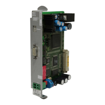
System Introduction Introduction to the RM2-DP12 System The RM2-DP12 module provides you with the possibility to create, at the PROFIBUS-DP, a modular slave node with modules of the CL200 PLC module range. Fig. 1 RM2-DP12 1070 072 449-102 (01.12) GB... - Page 15 System Introduction The RM2-DP12 can be plugged into a CL200 mounting rack. It is supplied with a 24 V voltage and provides the internal 7.5 V supply voltage (1.2 A) for the in- and output modules. The module is provided with a singular module width and must be operated on slot 1.
-
Page 16: Power Supply
The RM2-DP12 necessitates an external 24 V power supply. The X10 connection for the 24 V power supply is located on the front panel. The RM2-DP12 module provides the internal 7.5 V power supply for the in- and output modules, so that an additional power supply unit for the internal supply of the modules is not necessary (also refer to I/O modules). - Page 17 Power Supply 1070 072 449-102 (01.12) GB...
-
Page 18: Profibus-Dp
PROFIBUS-DP PROFIBUS-DP Connection The RM2-DP12 and the PROFIBUS are connected via a 9-pin D-Sub plug which, for security reasons, should be screwed to the RM2-DP12's D-Sub socket. The X71 connection for the PROFIBUS is located on the front panel. The pin assignment corresponds to the PROFIBUS standard. -
Page 19: Setting Of Bus Address
RROFIBUS-DP Setting of Bus Address Each node at the PROFIBUS-DP must receive its own bus address. The bus address of the RM2-DP12 module is set by means of the S1 DIP switch. Þ Þ Þ Þ The set bus address will only be scanned during run-up, i.e. when the supply voltage is applied to the X10 connection. -
Page 20: Status Display
Status Display Status Display The operational statuses of the module are shown on a 7 segment display. Furthermore, the operational statuses are divided into 4 groups: • Static display • Flashing display • Alternating display with starting signal F • Alternating display with starting signal H 7 segment display: SEG_A SEG_F... - Page 21 Hardware test active: Carry out the hardware test in POWER_ON status. Peripheral bus Init: One or more peripheral bus modules are still in their initialization phase and hold the RM2-DP12 module in POWER_ON status. 1070 072 449-102 (01.12) GB...
-
Page 22: Flashing Display
Status Display Flashing Display Display Status Overflow of DP in-/output data buffer Overflow of DP input data buffer Overflow of DP output data buffer Overflow of DP configuration data buffer No I/O assignment found General peripheral bus error Peripheral bus time out Peripheral bus initialization error Invalid DP bus address... -
Page 23: Alternating Display With Starting Signal F
Status Display Peripheral bus initialization error: Possible causes for errors are: • Hardware error of an I/O module. • Missing 24 V power supply of the POS-SA 1/2 module. • Module number in the input or output area is given twice. Invalid bus address: The PROFIBUS-DP address set on the S1 DIP switch lies outside of the permissible range (valid range: 2-125). -
Page 24: Alternating Display With Starting Signal H
Status Display Alternating Display with Starting Signal H Internal hard- or software error. 1070 072 449-102 (01.12) GB... - Page 25 Status Display 1070 072 449-102 (01.12) GB...
-
Page 26: I/O Modules
I/O Modules I/O Modules Supply The RM2-DP12 module provides the internal 7.5 V supply voltage for the in- and output modules. The 7.5 V supply voltage can be loaded with a maximum of 1.2 A. Þ Please observe the limit value of the current! -
Page 27: Addressing
Connection of an absolute encoder with a data width of 16 bit to a digital input module. Expansion Possibilities With the RM2-DP12 module, six I/O modules can be operated on one mounting rack. If this is not sufficient for an application, there are two ways of expansion: •... -
Page 28: Limits Of Expansions
I/O Modules Limits of Expansions With regard to the expansion possibilities of the CL200 peripherals, the following limit values exist for the modular DP station: • Please observe the limit value of the current! The I/O modules' maximum current input from the peripheral bus supply (7.5 V) must not exceed 1.2 A! •... - Page 29 I/O Modules 1070 072 449-102 (01.12) GB...
-
Page 30: Ambient Temperature
Ambient Temperature Ambient Temperature The RM2-DP12 module is operated without a fan. In order to avoid a thermal damage of the RM2-DP12 module, please comply with the following: • The ambient temperature must not exceed 55°C. • Ensure sufficient air circulation in order to avoid heat accumulation. - Page 31 Ambient Temperature 1070 072 449-102 (01.12) GB...
-
Page 32: Dp Diagnostic Information
DP Diagnostic Information DP Diagnostic Information The RM2-DP12 module supports standard diagnostic information and the extended diagnosis possibilities of the PROFIBUS-DP. Among the extended diagnostic information, the RM2-DP12 supports the "identifier- related diagnosis", i.e. that for each I/O module 1 bit is reserved in the diagnostic buffer, which can indicate if the I/O module is under diagnosis or not. - Page 33 DP Diagnostic Information 1070 072 449-102 (01.12) GB...
-
Page 34: Technical Data
Dirt resistance: Degree of contamination 2 as per EN 1131-2 The RM2-DP12 module requires a dustfree environment. The housing and compartments in which the mounting rack is located must comply with the minimum degree of protection IP54 as per DIN VDE 0470-1. - Page 35 Technical Data Mechanical stress (shock and vibration resistance): Vibrations: Sinusoidal oscillations in all 3 axes as per IEC 1131-2 Frequency 10 - 57 Hz with 0.0375 mm constant amplitude with 0.075 mm occasional amplitude Frequency 57 - 150 Hz with 0.5 g constant amplitude, with 1.0 g occasional amplitude Shock: Impact resistance on all 3 axes as per IEC 1131-2,...
- Page 36 1070 072 449-102 (01.12) GB • HB SP • BRC/EP • Printed in Germany...
Need help?
Do you have a question about the RM2-DP12 and is the answer not in the manual?
Questions and answers