Advertisement
Quick Links
SERVICE BULLETIN
nd
Issue No: MG018
Date: 22
January 2016
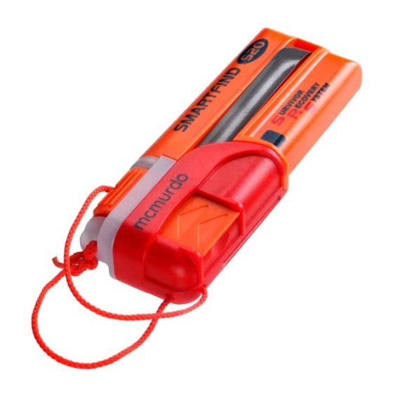
McMurdo S20 & Kannad Marine R10 AIS MOB Devices
Battery change & maintenance instructions
INTRODUCTION
1.1 Scope:
This document provides the instructions to enable routine servicing
of the S20 & R10 AIS MOB units.
1.2 Servicing equipment:
The following tools and equipment are required to carry out the
servicing detailed in this manual. Only authorised and trained
people are allowed to perform maintenance & service on these products. We advise it is
good practice that records of any maintenance or service performed are maintained.
Equipment:
AIS receiver
Hand tools:
Calibrated torque driver with attachments: 60 cNm
Small cross-headed screwdriver (No. 1 Pozidrive)
1.3 Antistatic precautions:
The electronics section of the product is sensitive to electrostatic discharge (ESD) which can
cause Immediate or hidden long term damage. It is important that the PCB is only handled
under suitable Antistatic conditions.
A fully grounded workstation, which has conductive surfaces to avoid the build-up of static
charge, should be used.
As a minimum, the operator must be connected to a good earth point through a resistance
of 1MOhm. This is usually achieved by wearing a suitable wrist strap.
1.4 Safety notices:
The product has been assessed as presenting negligible hazard in a sealed serviceable state.
Orolia Ltd, Silver Point, Airport Service Rd, Portsmouth, Hants, PO3 5PB, United Kingdom
Tel: +44 (0) 23 9262 3900 Fax: +44 (0) 23 9262 3998 Email:
service.uk@mcmurdogroup.com
Page | 1
Advertisement

Summary of Contents for mcmurdo S20
- Page 1 SERVICE BULLETIN Issue No: MG018 Date: 22 January 2016 McMurdo S20 & Kannad Marine R10 AIS MOB Devices Battery change & maintenance instructions INTRODUCTION 1.1 Scope: This document provides the instructions to enable routine servicing of the S20 & R10 AIS MOB units.
- Page 2 1.5 Safety analysis: The following table summarises the nature of the hazard which may be present when the unit is opened or serviced. 1.6 Hazard cause Hazard identification Precautions: Lithium battery Explosive risk, corrosive fumes, fire, Handle appropriately, avoid contact Biological hazard, Radio frequency, Physiological hazard Avoid close or prolonged exposure.
- Page 3 2. DISASSEMBLY 2.1: Remove the activation cap. The beacon will activate. Switch off the beacon by pushing and holding the ‘Off’ button – the beacon should switch off after approximately 3 seconds. NOTE: Do not allow beacon to operate for longer than 15 seconds. 2.2: Remove LED cap by removing 2 off Screws.
- Page 4 3. ASSEMBLY 3.1: Ensure the Foam Pad to the bottom of the cell pack. 3.2 : Ensure the replacement Sealing Gasket is fitted to the replacement LED cap assembly. Note: Ensure the gasket is seated correctly or product may fail the leak test. 3.3: Ensure the PCB assembly is seated correctly.
- Page 5 3.4: Fit battery assembly into casing, care should be taken to ensure foil insert is not damaged. Position the wires as shown. Connect the battery to the PCB. 3.5: De-press the battery counter reset button, the LED and buzzer will operate for a duration of 1 second when indicating a successfully reset.
- Page 6 3.7: Perform an ON/OFF test by pushing and releasing the ‘On’ button. The beacon should flash at least once and a beep should be heard with each flash. Switch off the beacon by pushing and holding the ‘Off’ button – the beacon should switch off after approximately 3 seconds.
-
Page 7: Final Assembly
4.3 Drying times A gross leak may still lead to water inside the unit. If this occurs, then disassemble the unit and dry its component parts in an oven at +40°C to +60°C. Most parts will dry in a few hours, However the battery pack traps water and should be left in the oven for at least 16 hours. - Page 8 Perform away from busy sea areas where the test transmission could confuse other AIS users. It is recommended to use a McMurdo M15 AIS receiver with AIS viewer running on Windows PC or similar AIS receive equipment to verify correct transmission after service.
- Page 9 8.2 Instructions: a) Arming Tab should be attached to the shorter end of the cord with a figure of 8 knot. Pull tight to hide the knot inside the tab like this: Figure of eight knot b) Fit the activation cap to the beacon – note this will switch on the beacon, so once fitted press and hold the ‘off’...
- Page 10 9. Rigging of the long lanyard length to the white body. 9.1: The unit maybe be rigged for either manual-only activation or semi-automatic depending on the user requirement. Semi-automatic operation requires an activation force created by the inflation of the lifejacket pulling off the red cap, which releases the antenna and turns the unit ON. Therefore, two methods of rigging the lanyard are permissible as follows.
Need help?
Do you have a question about the S20 and is the answer not in the manual?
Questions and answers