Advertisement
Quick Links
Overview
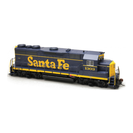
This application note describes how to install a
TSU-AT1000 into an Athearn HO Ready-To-Roll
EMD GP35.
Skill Level 2: The entire installation can be
completed in one to two hours with no
modification required to the model.
Bill of Materials
P.N.
Description
828039
TSU-AT1000 for EMD 567D Turbo
810113
16mm x 35.1mm Oval Speaker
Evergreen P.N.
9030
0.030" Sheet Styrene
For your convenience, Evergreen part numbers have
been listed above. Please visit their website at
www.evergreenscalemodels.com
Tools You Will Need
■ 25 W Soldering Iron
■ Rosin Core Solder
■ Wire Strippers
■ Wire Cutters
■ X-Acto Knife with #11 Blade
■ Miniature Screwdriver Set
■ Metal Straight Edge
■ Dial Calipers
■ Aquarium Sealant or Clear Silicone
Athearn RTR EMD GP35
Tsunami Digital Sound Decoder Installation Notes
■ Liquid Plastic Cement
■ Insulative Electrical Tape
■ Double-Sided Foam Tape
■ Masking Tape
■ Small Pliers
■ 30-32 Gauge Wire
Advertisement

Related Manuals for SoundTraxx Tsunami TSU-AT1000


Summary of Contents for SoundTraxx Tsunami TSU-AT1000
- Page 1 Athearn RTR EMD GP35 Tsunami Digital Sound Decoder Installation Notes Overview This application note describes how to install a TSU-AT1000 into an Athearn HO Ready-To-Roll EMD GP35. Skill Level 2: The entire installation can be completed in one to two hours with no modification required to the model.
-
Page 2: Installation
Installation Once all wires have been disconnected, the board can be removed. There is a clip on the bottom of the board that snaps onto a second Begin with removing the couplers and coupler clip on top of the motor. This clip also acts as boxes. - Page 3 Once the clip has been removed, solder a Unclip the retainer holding the worm gear to 3” piece of 30-32 gauge wire to the top of the the top of one of the gear towers by spreading clip so that it extends over the long end. After out the sides and lifting them free.
- Page 4 12. Reinstall the motor in the frame. Be sure to 16. The speaker for this installation is a small oval insert the drive shaft into the fl ywheel before speaker. Start by soldering two 6” pieces of reinstalling the screws for the motor mounts. 30-32 gauge wire to the terminals on the Install the driveline removed in Step 6 and speaker.
- Page 5 20. This model is equipped with 1.5V bulbs. The 21. Solder the speaker wires to the S+ and S- TSU-AT1000 has a provision for use with 1.5V terminals. Since only one speaker is being used, bulbs without the need for additional resistors. polarity is not important.
- Page 6 Left Pickup Left Pickup Motor ® New Dimensions in Digital Sound Technology 141 Burnett Drive • Durango, CO 81301 ©2013 Throttle Up! Corp. Phone: (970) 259-0690 • Toll Free: 888-789-7637 • Fax: (970)259-0691 All Rights Reserved Email: support@soundtraxx.com • Website: www.soundtraxx.com...
Need help?
Do you have a question about the Tsunami TSU-AT1000 and is the answer not in the manual?
Questions and answers