Table of Contents
Advertisement
Advertisement
Table of Contents

Related Manuals for Navico Simrad I3005


Summary of Contents for Navico Simrad I3005
- Page 1 I3005 / I3007 Operator Manual ENGLISH www.navico.com/commercial...
- Page 3 Preface Disclaimer As Navico is continuously improving this product, we retain the right to make changes to the product at any time which may not be reflected in this version of the manual. Please contact your nearest distributor if you require any further assistance.
- Page 4 Compliance statements Europe Navico declare under our sole responsibility that the product conforms with the requirements of: • CE under EMC Directive 2014/30/EU • European Council Directive 2014/90/EU on Marine Equipment modified by Commission Implementing Regulation (EU) 2018/773 (MED) - Wheelmark Ú...
- Page 5 Trademarks ® Navico is a registered trademark of Navico Holding AS. ® Simrad is used by license from Kongsberg. ® ® NMEA and NMEA 2000 are registered trademarks of the National Marine Electronics Association. ™ ™ and microSD are trademarks or registered trademarks of SD-3C, LLC in the United States, other countries or both.
- Page 6 Preface | I3005/I3007 Operator Manual...
-
Page 7: Table Of Contents
Contents Introduction About this unit Page layout Card reader 12 Basic operation Turning the unit ON Menu overview Backlight settings Screen capture Simulator mode 15 Pages Page options Selecting a page Missing or faulty data Predefined pages 22 Software setup Software setup overview Introduction to Lightweight Ethernet First time startup... - Page 8 42 Appendix Menu overview Terms and abbreviations Supported data LWE Transmission groups Contents | I3005/I3007 Operator Manual...
-
Page 9: Introduction
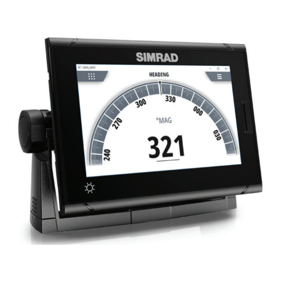
Introduction About this unit The I3005 and I3007 units are touch controlled color displays. The units support English language in menus and dialogs. The units are configured with multiple analog-style gauges as well as configurable digital data display layouts. Both I3005 and I3007 are approved for SOLAS vessels. Type approved pages The following pages are type approved: •... -
Page 10: Page Layout
Page layout Page selection button Picture freeze indicator Menu button Custom label Picture freeze indicator The image includes a picture freeze indicator. The small dot blinks at an interval of 1 second to show that the screen is alive and that information from sensors is updated. - Page 11 A memory card can be used for: • Software updates • Transfer of user data • System backup The protective door should always be securely shut immediately after inserting or removing a card, in order to prevent possible water ingress. Introduction | I3005/I3007 Operator Manual...
-
Page 12: Basic Operation
Basic operation Turning the unit ON The unit does not have a power key. The system will be ON as long as the power switch is on. Depending on your setup, the power switch can be the ignition switch or a separate power switch. -
Page 13: Backlight Settings
Backlight settings The display backlight can be adjusted at any time from the backlight settings dialog. To access the dialog: • Press the brilliance key Repeated short presses on the brilliance key cycles thru the preset backlight levels. Ú Note: All changes made to the display setup will apply to all units belonging to the same display group. -
Page 14: Simulator Mode
Simulator mode The simulate option lets you operate the unit without being connected to sensors or other devices. It is not possible to simulate commissioning and setup. If the unit is turned off while in simulator mode, this mode will still be active on next power on. -
Page 15: Pages
Pages Page options This display includes 10 predefined data pages, together with 5 template pages used for creating user defined pages. The predefined pages can be used as-is, customized, or replaced with user defined pages. Ú Note: The type approved pages cannot be customized. You can have up to 8 pages enabled, and only enabled pages can be selected by using the page selection button. -
Page 16: Selecting A Page
Pre-defined pages Template pages Boat speed Propeller RPM Trip Log ÷ Selecting a page Missing or faulty data If a data type is missing or if the data is out of scale, there will be no data reading on the display. Pages | I3005/I3007 Operator Manual... -
Page 17: Predefined Pages
Predefined pages Rudder Default page Customized page Page settings: Range scale (+/- 45°, +/- 70° or +/- 90°), commanded rudder angle, and custom label. Rate of turn Default page Customized page Page settings: Scale range (+/- 30°, +/- 120° or +/- 300°), and custom label. - Page 18 Heading Default page Customized page Page setting options: custom label. Depth history Default page Customized page Page settings: Time range (5, 10, 30 or 60 minutes). Changing time range Pages | I3005/I3007 Operator Manual...
- Page 19 Wind Default page Customized page Page settings: true wind calculation (relative to vessel or relative to ground), orientation (relative to vessel or relative to ground), and custom label. Boat speed Default page Customized page Page settings: scale limit (25 or 50 knots), source (STW or SOG), and custom label.
- Page 20 Page settings: labels (propeller shaft pitch angle: ahead/astern, or thruster pitch angle: port/starboard), and custom label. Engine RPM Default page Customized page Page settings: scale limit (200, 500, 1000, 3000, 7000 or 10 000), and custom label. Propeller RPM Default page Customized page Page settings: scale limit (100, 125, 150, 200, 250, 300, 400 or 450), and custom label.
- Page 21 The total trip distance can be set and STW toggled on/off from the trip log settings dialog, refer to "Software setup" on page 22. Starting/stopping and resetting the trip log Pages | I3005/I3007 Operator Manual...
-
Page 22: Software Setup
Software setup Software setup overview Prior to use, the system requires a number of settings to be configured in order for the system to perform as expected. Most settings are intended to be configured by the technician commissioning the system, by the operator at first use, or by a technician after servicing or replacement of system parts. -
Page 23: First Time Startup
First time startup When the unit is started for the first time, or after a reset, the unit displays a series of dialogs. Respond to the dialog prompts to make fundamental settings. You can perform further setup and later change settings using the system settings dialogs. -
Page 24: The Settings Dialog
The settings dialog The software setup is done from the settings dialog. Access control The parameters in the settings dialogs are intended for system setup and service engineers. These parameters are protected, and they are only available by entering the pin: 1947. When the password is entered, all settings are accessible. -
Page 25: Page Settings
Time Controls the local time zone offset, and the format of the time and date. Restore defaults Restores selected settings to default factory values. Files File management system. Used to display selected content of the unit for export, and to browse storage devices connected to the unit. - Page 26 Enable/disable a page To make a page available for display it has to be enabled. Replace a page Pages can be replaced with one of the other predefined pages, or by a template page if you want to create a custom page. Creating and editing a custom page A custom page is created in a two steps process: Replace one of the active pages with a template page, refer...
-
Page 27: Trip Log Settings
If the page has multiple data fields, select the field you want to change. Use the menu option to save or cancel the changes. Change page settings The pre-configured pages have different options for customizing the page layout. For options available for each page, see details in "Pages" on page 15. Trip log settings Software setup | I3005/I3007 Operator Manual... -
Page 28: Units Settings
Use STW Used for setting the speed source to be speed through water. When enabled, the speed data will be STW rather than speed over ground (SOG) on the trip log page. Set log Allows for manually entering the total trip log distance. Units settings Used for specifying the units of measurement. - Page 29 Ú Note: AIS transponders typically operate at NMEA 0183-HS (high speed), and will require the baud rate to be set to 38,400. NMEA 2000 installer notes Used to identify a device in the NMEA 2000 device list. Serial input sentences This list allows control over which sentences that are received from other devices from the NMEA 0183 port.
- Page 30 Use analog input to control backlight level This option must be turned on if an external potentiometer is to be used to control the backlight level. Calibration data Calibration data is used to calculate a value from the signal input from the sensor.
- Page 31 Configure digital port Ú Note: A unique SFI must be assigned to the digital port if this is to be part of the LWE network. Speed log input It is possible to configure the digital port for speed input. Ú Note: Only speed logs outputting 200 pulses per nautical mile are supported.
-
Page 32: Calibration
System Function ID (SFI) A unique SFI must be assigned to each port that is to be part of the LWE network. If no SFI is entered (remaining with the default 0000 value), the device will not be visible on the LWE network, and it will not share any data. - Page 33 Ú Note: Serial ports are represented as virtual NMEA 2000 devices. NMEA 2000 setup Device list Selecting a device in this list will bring up additional details and options for the device. All devices allow allocation of an instance number in the configure option.
- Page 34 Some devices show additional options specific to the device. For example the Calibrate option, to allow easy setup of a device. For device specific details, refer to the device documentation. Global sources Auto Select The Auto Select option looks for all sources connected to the device.
- Page 35 Calibration An offset (positive or negative) can be applied to correct data inaccuracies from NMEA 2000 sources. Ú Note: Any calibrations made here will only be applied locally to this unit. Other devices on the network will not have these offsets applied.
- Page 36 several units are connected via a network. By assigning several units to the same group, a parameter update on one unit will have the same effect on the rest of the group members. If any of the settings require discrete control, set the group to None. Damping If data appears erratic or too sensitive, damping may be applied to make the information appear more stable.
- Page 37 Each of the devices must be configured with: • a unique 4-digit Lightweight Ethernet SFI for the selected serial port • the NMEA 2000 source, selected from the list of available devices • Installation notes, used to identify the device Software setup | I3005/I3007 Operator Manual...
-
Page 38: Maintenance
Maintenance Preventive maintenance The unit does not contain any field serviceable components. Therefore, the operator is required to perform only a very limited amount of preventative maintenance. Cleaning the display unit To clean the screen: • A micro-fiber or a soft cotton cloth should be used to clean the screen. -
Page 39: Backup And Restore Of System Data
Restore global settings This option clears the global NMEA 2000 source selection on all networked devices, and resets all local settings to factory default. After a global reset you need to configure all NMEA 2000 and local sources again when the unit restarts. Restore local settings Resets all local settings to factory default. -
Page 40: Software Updates
The product website has information about available software updates. Update the software from a storage device You can download the software update from www.navico.com/ commercial. Transfer the update file(s) to a compatible storage device, and then insert the storage device in the unit. - Page 41 Maintenance | I3005/I3007 Operator Manual...
-
Page 42: Appendix
Appendix Menu overview Main menu Level 1 Level 2 About... Time range (Depth history <Preset options: (5, 10, 30, 60 page only) min)> Trip log (Trip log page only) Start/Stop trip log Reset trip log Settings... See "Settings menu" on page 42 Settings menu Level 1 Level 2... - Page 43 Level 1 Level 2 Units Distance Distance small Speed Wind speed Angular speed Depth Heading Temperature Volume Pressure Baro pressure Local port setup Configure NMEA 0183 port 1 Configure NMEA 0183 port 2 Configure analog port Configure digital port Calibration Magnetic variation Network Display sources >...
-
Page 44: Terms And Abbreviations
Terms and abbreviations Automatic Identification System ATON Aid to Navigation Bearing Bearing To Waypoint Bearing Waypoint To Waypoint Course Over Ground Course Course To Steer DGPS Differential GPS Dead Reckoning Digital Selective Calling Distance To Destination Distance To Waypoint EGNOS European Geo-Stationary Navigational Overlay System EPIRB... - Page 45 MSAS Multi-functional Satellite Augmentation System Odometer RAIM Receiver Autonomous Integrity Monitoring Rate Of Turn RTCM Radio Technical Commission For Maritime Search And Rescue SBAS Satellite Based Augmentation System System Function ID Speed Over Ground Speed Through Water Time To Destination Universal Database Uninterruptible Power Supply Universal Transverse Mercator (coordinate...
-
Page 46: Supported Data
Supported data NMEA 2000 compliant PGN list DESCRIPTION 59392 ISO Acknowledgement 59904 ISO Request 60928 Address Claim 126208 Group Function 126992 System Time 126993 Heartbeat 126996 Product Info 126998 Configuration Information 127233 Man Overboard Notification 127237 Heading/Track Control 127245 Rudder 127250 Vessel Heading 127251 Rate of Turn 127252 Heave... - Page 47 DESCRIPTION 128259 Speed, Water referenced 128267 Water Depth 128275 Distance Log 129025 Position, Rapid Update 129026 COG & SOG, Rapid Update 129029 GNSS Position Data 129033 Time & Date 129539 GNSS DOPs 129540 AIS Class B Extended Position Report 129545 GNSS RAIM Output 129549 DGNSS Corrections 129551 GNSS Differential Correction Receiver Signal...
- Page 48 NMEA 0183 supported sentences TX / RX - AIS/DSC Ú Note: AIS sentences are not bridged to or from NMEA 2000. TX / RX - GPS GGA5 Appendix | I3005/I3007 Operator Manual...
- Page 49 TX / RX - Navigation TX/RX - Echosounder TX / RX - Compass Appendix | I3005/I3007 Operator Manual...
-
Page 50: Lwe Transmission Groups
TX / RX - Wind TX / RX - Misc. LWE Transmission groups Input Output MISC NAVD PROP SATD TIME USR1 to USR8 Appendix | I3005/I3007 Operator Manual...
Need help?
Do you have a question about the Simrad I3005 and is the answer not in the manual?
Questions and answers