
Related Manuals for Navico SIMRAD ECDIS900


Summary of Contents for Navico SIMRAD ECDIS900
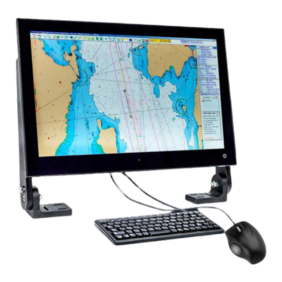
- Page 1 ECDIS900 Operator Manual ENGLISH Software version: 5.3.0 www.navico-commercial.com Scan here to save a copy...
- Page 3 LIABILITY FOR ANY USE OF THIS PRODUCT IN A WAY THAT MAY CAUSE ACCIDENTS, DAMAGE OR THAT MAY VIOLATE THE LAW. This document represents the product as at the time of publishing. Navico Group reserves the right to make changes to the product and/or specifications at any time without notice.
- Page 4 • Simrad® is a trademark of Kongsberg Maritime AS, Licensed to Navico Group. • C-MAP® is a trademark of Navico Group. • NMEA® is a trademark of National Marine Electronics Association. • NMEA 0183® is a trademark of National Marine Electronics Association.
-
Page 5: Table Of Contents
Contents Introduction The ECDIS system ECDIS requirement System overview 11 System components Software components Hardware components 15 Basic operation Start-up Turning the system on and off Adjusting display brightness Set standard display Changing workstations Switching to Administrator mode Service mode Operation mode Switching between charts Zoom In/Out... - Page 6 Chart borders Chart settings ARCS 89 Routes Creating route using keyboard Creating route using mouse Download from GPS Modifying a route Route properties Route plan overview Parallel index Load, unload, and delete route functions Synchronize a route between workstations 100 Upload routes over the LAN 100 Check a route 102 Danger highlighting 103 Route options...
- Page 7 121 DSPNor Radar kit 122 Radar overlay 122 Display settings 123 Tools 125 Alert management 127 List of alerts 128 Other types of alarms 128 User-defined alarm 129 Anchor watching 130 Harbor mode 131 Automatic Identification System (AIS) 133 Broadcasted data 133 Targets 134 AIS target display 135 Sleeping target...
- Page 8 179 Sector option 179 Parallel track option 180 Appendix 180 Terms and abbreviations 181 Profile configuration parameters 184 Troubleshooting 184 Encryption scheme errors in ENC 185 Common errors in ARCS chart management 186 Maintenance Contents | ECDIS900 operator manual Operator Manual...
-
Page 9: Introduction
Both hardware and software in the system are ECDIS type approved. The type approval certificates are available from the product site on www.navico-commercial.com The operational area of this ECDIS using ENC charts is between latitude 85° N and 85° S. -
Page 10: System Overview
System overview The Simrad ECDIS900 interfaces with navigational equipment in accordance and compliance with the IMO's ECDIS performance standards. It is designed to interface with other equipment that enhances the Watch Officer's ability to safely navigate and manage information. The ECDIS900 is designed to work on Windows operating systems. -
Page 11: System Components
System components Software components Application manager Application manager is a Windows shell that is installed by default on ECDIS computers. It enables users to manage and gain access to start menu, task bar and system trays. It also provides the standard desktop environment as well as graphical user interface for accessing the file management functions of the Windows operating system. - Page 12 Switch off the computer button Click once to turn off the computer. Security settings button Click once to display the security settings dialog. See "Security settings" on page 12 for more details. ECDIS900 button Click once to open the running ECDIS. Ú...
-
Page 13: Hardware Components
Operation Mode button Click this button to enable Operation Mode. This is the default mode of the ECDIS system after the installation process. See "Operation mode" on page 16 for more information. Service Mode button Click this button to switch to Service mode. This option is used by technicians to configure and service the ECDIS. - Page 14 Trackball The trackball is used as a pointing device to select ECDIS system menus and dialogs. Alarm Panel The Alarm panel is the audio source for the system. The unit gives an audible alert for any faults from the system, including power supply failure. Audible alerts are mandatory for any systems requiring Wheelmark certification.
-
Page 15: Basic Operation
Basic operation Start-up The ECDIS900 system is switched on by pressing the external power switch of MK15B or MK5B computers. The system should be left with the power ON. When power is switched on, the operating system will be started, automatically followed by the system program. -
Page 16: Set Standard Display
Set standard display Click the icon once or press F7 to enable the standard mode of the ENC display. Ú Note: When the system is using ARCS chart, clicking this icon will also enable the system to display the original ARCS chart scale. Ú... -
Page 17: Switching Between Charts
Switching between charts To switch charts, right-click on the current chart area to display the pop-up menu. Hover your cursor over the Other charts option and select the chart database you want to use. You can also press the F9 key on the keyboard to select another type of chart database. Pressing the F9 key will only select chart databases that are configured in the quick switch option. -
Page 18: Print Screen
The list of scales displayed in the static information console depends on the chart type being used. A check mark (✓) indicates that the scale is currently used. An exclamation mark (!) indicates that an ENC cell with this compilation scale is installed and available. Navigators should always check the approved scale before use and during route monitoring. -
Page 19: The User Interface
The user interface The main window The main window is divided into predefined areas as shown in the figure below. Chart area Toolbar panel Window title bar Console area Window title The window title bar is a section at the top of the main window which displays the name of the application. -
Page 20: Toolbar Panel
Toolbar panel The Toolbar panel provides quick access to common functions directly related to the watch officer's duties. Man over board icon New logbook record icon Event icon Logbook icon Zoom in icon Set manual target icon Zoom out icon Target table icon Standard Display icon Target prediction icon... -
Page 21: Chart Area
Chart area The Chart area is a graphical representation of vector or raster charts based on IEC standards. This enables users to view all aspects of safety, interoperability, efficiency, compatibility and environmental impact of ECDIS900. North symbol The North symbol enables users to view that the top of the chart is the true north not a magnetic north towards which a compass points. - Page 22 Scale indicator Current scale Displays the current scale of the chart. The panel can be located in the console area or in the toolbar area. Below is an example of an approved scale view: Overscale If the current scale is two times larger than the compilation scale of the ENC cell, the scale panel displays an overscale warning.
- Page 23 Other panels Safety contour panel When vector charts are in use, two different depth values are displayed in the Safety contour panel: • The safety contour value that is selected and added by the mariner. • The safety contour that is available in the chart cell located under the ship’s position. Ú...
- Page 24 Tools panel The Tools panel consists of the following tabs: • Legend • Editors • Radar • Weather • Active leg Click on the tab name to switch between Tool panels. Legend panel The Legend panel displays information about the loaded ENC cells or raster chart under the ship’s position and indicate some alerts.
- Page 25 Indications warnings The warnings can be indicated with highlighted texts and icons that are displayed in the Legend panel. Warnings can be as follows: An Overscale message indication that is displayed when the chart is overscaled. • A Better chart exists warning message that is displayed when the ship position is •...
-
Page 26: Security And System Settings
This will help ensure the operational reliability and security of the ECDIS and supporting systems. To reset your password, contact NAVICO at cmd.service@navico.com. Security and system settings | ECDIS900 operator manual... -
Page 27: Ecdis Settings Option
ECDIS settings option From the toolbar panel, click the Options button to open the ECDIS settings option dialog. This enables mariners to manage the following: • Customize the console layout • Adjust the ECDIS local time and chart time • Select the route parameters by default •... - Page 28 Lock a configuration It is recommended to lock the editing once the configuration is properly defined to avoid unwanted changes. To lock, tick the Freeze configuration checkbox. Loading a configuration The Console configuration options dialog enables mariners to choose an existing configuration to be defined in the system.
- Page 29 Restoring data Click the Restore button and select the back-up folder to restore all data. Warning: The restored data replaces the current data used by ECDIS and data created after the back-up will be lost. Creating profiles You can save custom ECDIS parameters configuration as a specified profile. One the configuration has been defined, set the profile name, and click the Create profile button.
-
Page 30: Tools For Safe Navigation
Tools for safe navigation Man over board (MOB) This enables users to keep an MOB waypoint record of the exact location that someone went overboard and send AIS warnings to other vessels. The AIS warning alerts nearby vessels to request assistance in the rescue operation or simply to stay clear as the situation requires. -
Page 31: Selecting Chart Area
The event information displays the time of the event (UTC), course over ground to the next waypoint (COG), speed over ground (SOG), and user comments. Selecting chart area To view the predefined scale of your chart area, click the Select area icon from the toolbar panel. - Page 32 Creating a new display area manually To create a position of a chart area manually, click the New area by keyboard button and input the desired name, LAT, LON and scale. Click the OK button to save the changes. Ú Note: To switch the current chart area to a new chart area, double-click the chart name or select the chart name and click the Center on button.
-
Page 33: Center On Ship
Ú Note: A list of chart areas is created for every specific type of chart. The list created for ENC chart is valid only for this type and cannot be used with ARCS charts and vice versa. Center on ship To center the chart on the ship, click on the Center on ship icon. -
Page 34: Targets
Targets Setting a target To plot a manual target, click on the Set target icon. For more details about manual targets, see "Manual target" on page 119. Target list To display the target list, click on Target list button. • Double-click on the target name to center the chart on the target. -
Page 35: Loading/Unloading Objects
AIS message, start and stop AIS server The system allows sending and receiving short messages to/from another AIS. Click the AIS messages... button to display the AIS messaging dialog. Customize table Click Customize table to display the Customize target table dialog and select the items you want to display. -
Page 36: Point To Point, Range And Bearing
Ú Note: Use the object menu for removing a single VRM/EBL. To remove all VRM/EBL, use the Delete key from the keyboard or the Clean chart function from the chart menu. Point to point, range and bearing To set two points at a fixed range and bearing from each other, click the Point to point, range and bearing button. - Page 37 Updating the vessel information To modify the ship name, type and size, follow the steps below: Click the Ship properties icon to display the Ship properties dialog. Select the General tab and modify the vessel parameters accordingly. Ú Note: Call Sign and IMO number are password protected and can only be modified if the correct password is entered.
- Page 38 Enabling D.R. Click the D.R. tab to display the Dead Reckoning dialog. Tick on/off the Enable Dead Reckoning to enable/disable Dead Reckoning option. When the Dead Reckoning mode is enabled, a warning message similar to the one shown below is displayed: Ú...
- Page 39 Managing track recordings Click the Track tab to display the Track dialog. Tick on/off the Show active track to show/hide the active tracks. To set a desired number of recording days, use the arrows beside the Record ship track for the last option.
- Page 40 Ú Note: Warnings are highlighted in yellow with black border. Ú Note: All dangers in all chart layers are highlighted. If a danger is not on the current visible layer, it is highlighted when it is in the guard zone sector. Click inside a ship guard zone to view the list of dangers and display the detailed overview of the alarm type.
- Page 41 Display tab Color settings You can define colors of the ship symbol and shape plot. To set the color, click the Day color button. The color dialog is displayed. Select the desired color and click OK to save the changes on the ship symbol color and shape plot color.
- Page 42 Scaled icon Tick on the Scaled icon check box to display the ship icon with its right scale. To display a line to the active waypoint tick on the proper check box. Set the desired Vector time value. The length of both the ship’s vector and the target’s vector depends on the ship’s speed and the vector time value.
- Page 43 GPS antenna The GPS antenna is displayed as a circle with a cross inside it. There are two ways to change the antenna position: • Double click on the antenna’s name in the list. The position settings dialog appears. Set the position and click OK. •...
-
Page 44: Show Port List
This table is used in the Predictor module to calculate the future position of the ship when it turns. For more details see the chapter "Predictor" on page 171. AIS tab If AIS is connected to the ECDIS workstation, ECDIS900 receives from the transponder the own ship’s parameters set up in the AIS transponder. - Page 45 Tide ECDIS Tide Ú Note: Double right-click the Tide button to display a window listing the tide stations available on the chart. Left-click to highlight the tide station and double-click to open the station properties dialog The small tide icon displays the tide level at the current chart time in red and small black oriented arrows indicate rising or falling tide.
-
Page 46: Weather
Ú Note: Local area forecasts are 5-7 days only. The 9 days forecasts are for ocean areas. Ú Note: NAVICO disclaims responsibility for grib&grib2 files supplied by the providers if this data is not displayed correctly. Tools for safe navigation... - Page 47 A weather file includes several layers with data of defined period. For instance 5 days forecasts for wind and pressure situations, with weather data every 12 hours. The ECDIS interpolates the data in time and position making it possible to display continuously over a period of time and a geographical area all data included in the file.
- Page 48 Weather layers The following layers can be available: current temperature pressure visibility waves wind typhoon swell Use the settings dialog to define colors and other layer parameters. Layers illustration It is possible to display one or more forecast layers. Each layer has four parameters to display that can be switched on or off: •...
- Page 49 • Isoline • Direction • Text info Ú Note: No more than one layer can be filled in. Some layers have the direction parameter unavailable Example The following image is an example of the wind display with all parameters turned on: Ú...
-
Page 50: Ship Profile Management
Ship profile management This module is specially designed to suit the pilot's needs. The pilot builds his own ship’s profile database and can select the proper profile when entering a ship. A ship’s profile contains all ship and safety parameters settings including: •... -
Page 51: Charts
Charts Warning: Chart data and navigational features are intended for general guidance only. They do not replace a human navigator and should not be relied on as a sole or primary source of navigation. Only official government charts and notices to mariners contain all information needed for the safety of navigation. - Page 52 on page 67), or the update history (see "Update history" on page 69). When errors occur during chart management a message window displays the type of error. • Install and update ENC charts on the Planning station and copy the chart database onto a remote PC (see "Multi ECDIS workstations in LAN"...
- Page 53 When this zone is displayed, the indication No ENC data appears on the Legend panel (see "Legend panel" on page 24). Moving around the chart Automatic scrolling The ECDIS900 automatically scrolls the chart in the following cases: Route or user object plotting To plot a waypoint or a user object outside the current S57 chart area, move the cursor in the desired direction, and the chart will automatically scroll in that direction.
- Page 54 Manual scrolling Use a mouse and keyboard for scrolling charts. Locate the cursor near the chart edge of the chart area and a pan pointer will appear, pointing in one of eight directions, depending on where the cursor is located along the chart edge.
- Page 55 Automatic chart selection Set follow the ship To activate the Follow the ship mode, right-click anywhere on the chart and select the menu item Follow the ship. Operating in the Follow ship mode, the ECDIS900 automatically moves the current chart or loads new cells according to the ship’s movements.
- Page 56 The default projection is Cylindrical, which allows displaying a chart in a proper way even in high latitude areas. Depths Deep and shallow contours can be displayed in two different colors. Tick the checkbox for Use two colours for waters option to switch colors. Safety contour •...
- Page 57 Seamless ENC/AVCS If AVCS charts are installed together with ENC, both type of charts can be displayed in seamless mode. This means that for the area of the screen not covered by ENC charts, AVCS charts are used to complete the coverage. Seamless ENC/ARCS If ARCS charts are installed together with ENC both type of charts be displayed in seamless mode.
- Page 58 When Usage range is selected the scan of the cells is limited by the two usages selected by the user (From coastal to berthing in the example below). Toggle on the Disable SCAMIN impact to display all information at any chart scale. Examples Three charts are displayed with different values of depth and deep contour settings.
- Page 59 Next, the Safety contour value is changed: Chart properties To view the chart cell’s properties or to display information about an object of the chart, right-click somewhere on the chart or on that particular object and select Properties. Alternatively, press F4 when the cursor is on the chart. ECDIS scans the ENC database to find all objects present under the clicked point, highlights these objects on the chart, and displays information concerning them and the cell the objects belong to.
- Page 60 Areas The Areas tab displays administrative information and area object data. By default, category C objects are not displayed in the list. Click the Cat C button to make them visible. To copy the entire list of area properties, click the Copy button. If the area has notes, the information symbol is displayed.
- Page 61 If no notes or pictures are in the menu, the selected cell has no associated files. To copy the entire information of the tab, click the Copy button. More The More tab contains additional information about objects located under the cursor and displays the S-52 Presentation Library version.
- Page 62 You can expand several of all sectors and set the range value. It helps to control the navigation very precisely when sailing towards the light or within selected chart sectors. History of updates The History of updates tab displays the list of updates for the cell (or cells if there are more than one cell is under the cursor).
- Page 63 Chart management Click the Chart management button to open the Chart management dialog. Ú Note: The chart management is available from this dialog only. Type of charts The horizontal tabs are for the chart types Chart collection The vertical tabs are for the chart collections. The protected collections are: PM: Primar •...
- Page 64 Ordering the permits To order permits, contact your chart provider. Add permit by file The permits are delivered as 2 files, save the files onto a USB memory stick. Insert the USB memory stick into the USB port and select the directory containing permits files. A message window gives information about the status of the installed permits and about eventual errors.
- Page 65 Click the Install SA certificate button and browse folder to get *.crt file certificate. Ú Note: The SA certificate can be downloaded from: https://iho.int/uploads/user/pubs/ standards/s-63/S-63_SA_Certificate_Exp_2033.zip Install charts ENC charts can be installed from a DVD or an external USB memory drive from a folder located on a remote PC.
- Page 66 Ú Note: European ENC charts and updates that are distributed by Primar and UKHO are delivered as Base CD which contains the chart database issued at the time indicated on the label, and as Update CD which contains updates for the charts from the Base CD. Ú...
- Page 67 • ECDIS rejects corrupted update files and files with wrong extension or wrong name. • ECDIS checks that updates are applied in the right sequence. If one update is missing the next updates are rejected. Example: Single charts have update files with a specific order number, which is the suffix of the file: for example Jp54nvpr.002 is the second update file for the Japanese chart called Jp54nvpr.
- Page 68 Ú Note: If the selected session of update contains modified objects, it will be listed in the bottom frame of the dialog. The cell names are identified as follows: • Deleted cells are marked with red circles and a plus (+) sign. •...
- Page 69 Use buttons Before Update ## and After Update ## for switching on and off the result of the update. ## indicates the number of selected update. Display updates under the route Right-click on the route and select the Display updates under the route item from the list. Ú...
- Page 70 Multi ECDIS workstations in LAN When the chart installation and updates are done on one station, ECDIS offers the option to copy the updated database over the network, automatically updating all ENC databases in other stations connected to the LAN. Proceed as follows: Install and/or update ENC database on the planning station.
- Page 71 Chart collection status report You can get a report for any chart collection which is available in the Chart management dialog. Open the Chart management dialog. Select a chart collection. Click the ENC status report button, the report is open. If the selected collection contains more than 1000 charts, the system proposes to specify prefix for reducing the number of charts.
- Page 72 Information Right-click on red area and display T&P notice information in Areas tab. Update request and response The online update is possible when the PC is connected to Internet. This can be done in different ways: • The ECDIS PC is connected to the LAN and a PC on the LAN is the Internet access server with the chart provider software installed.
-
Page 73: Chart Borders
• The ECDIS PC has the chart provider software installed and uses a modem and the connection with the Internet provider is established manually. • A GSM is connected to the PC with the chart provider software installed and the connection with the Internet provider is established manually. -
Page 74: Chart Settings
Chart settings When an ENC chart is first displayed, the cell is displayed at the largest scale available in the SENC for the displayed area and the standard display provided. When several cells appear on the display the boundaries between cells are displayed. Ú... -
Page 75: Arcs
Ú Note: Any change of the Standard configuration triggers the alert indication. The indication is displayed on the Legend panel of Console area. For details, refer to "Legend panel" on page 24. The Standard configuration specifies the set of layers only. Color scheme and Presentation parameters can be changed without triggering an alert. - Page 76 ARCS charts are scanned copies of paper charts. A displayed ARCS chart includes the same information as appears on the copied paper chart. Source information about each chart is accessible from the ARCS properties dialog. Copy protection ARCS charts are copy protected with a dongle. In order to use and display ARCS charts in ECDIS it is necessary to: •...
- Page 77 After three failed attempts, the system does not allow the user to enter the PIN again for a certain period of time. If the problem persists, contact NAVICO support. Chart management Management of the ARCS chart database is carried out within the Chart management dialog.
- Page 78 The only type of ARCS license available is: Navigator Service. This service is designed for commercial ships that require a fully up to • date chart outfit. The user will be licensed to a specified chart holding for a defined period of time.
- Page 79 Click CTRL + Install selected charts button to select CD in a shared drive in the LAN. The charts with a valid installed permit are displayed with a green spot in the left hand column. If the permit is not valid the spot is red. Select the chart or charts to be installed and then click the Install charts button.
- Page 80 Ú Note: If a large number of charts are involved the process may take some time. Checking updated objects on the chart To check what has been updated, it is possible to temporarily switch between the display of updated chart and the original chart. Select the option Display updated tiles borders in the Chart settings dialog to display the borders of updated tiles.
- Page 81 - All tiles that have been updated since the base chart was issued. - The tiles have been updated only in the latest update procedure. Checking the updated objects on the chart Select the option Display updated tiles borders in the Chart settings dialog to display the borders of updated tiles.
- Page 82 The color of the chart indicator indicates the chart permit status: Green – the chart permit is valid. • Yellow – permit warning. The chart permit must be updated. • Red – the chart permit is not valid. • There are two ways to select a chart to be loaded: Click on the chart number and click Load chart.
- Page 83 • The user can zoom out to show half the chart area on the screen (medium scale) and out again to show the whole chart in overview (low resolution). • The user can also zoom in to display the chart at High resolution (Original scale * 2), Highest resolution (Original scale * 4).
- Page 84 Toggle the box Display Chart Borders to highlight the charts available on the hard disk. Ú Note: Clicking on the borderline of the chart displays information about the chart. Tick the Display updated tiles borders box to highlight the tiles which have been updated since the original chart was issued.
- Page 85 The notes belonging to the current charts are listed in the ARCS notes menu. Selecting one of the notes opens a window and shows the notes. Chart collection status In Chart management dialog, click the button Print collection status to get the current chart collection status.
- Page 86 To switch on the seamless mode tick the with ARCS check box in the Seamless Chart display group. The default state is Simple scale. To get the best scaled ARCS displaying for the chart area, tick on the Full scale. Seamless ENC/ARCS It is possible to display the best chart coverage for the area using all available chart collections.
- Page 87 Display strategy When ENC cells do not cover the whole screen, ECDIS900 looks for an ARCS chart with the closest scale within the limits of 4 times the current scale. ARCS chart is then eventually shifted according to its datum and zoomed according to the scale in use. If no ARCS chart is found, the general ENC background chart is used to complete the coverage.
- Page 88 The object outline changes to red to underline that it has become an alarm object. The width is one pixel and the area is not filled. Where the alarmed object is a point, this is surrounded by a red rectangle. Monitoring user alarm When the ship’s guard zone intercepts an alarmed object, an alarm is triggered.
-
Page 89: Routes
Routes Warning: Routing functions are intended for general route guidance only, and are not intended to be precisely followed or relied on as the operator's only reference source. It is the operator’s sole responsibility to review the suggested route against official publications and situational awareness. A route is defined as the chosen path between two ports. - Page 90 Create a route graphically Click the New route tool on the toolbar and then click on the chart at the point where the route should begin. A waypoint (WP 001) indicated by an orange circle is placed at this point. Double-click to set the end point of the route.
-
Page 91: Download From Gps
The screen covers a limited part of the chart. When a new waypoint has to be plotted outside of the screen area in view, ECDIS gives the user the possibility to scroll and zoom without deactivating the New route tool: •... -
Page 92: Modifying A Route
To send a route, select the Routes menu in the Sensor monitor toolbar and click the Send route. Modifying a route A route may be modified in several ways, but cannot be modified whilst locked or active. Move a waypoint •... -
Page 93: Route Properties
cursor to the desired position. The new segment will display the appropriate length and heading. • To stop adding new waypoints double-click on the last waypoint entered. Delete a waypoint • Locate the cursor on a waypoint that is to be deleted, right-click and select the menu item Delete. - Page 94 Name: name of the route that can be edited • Departure: name of the departure port • Arrival: name of the arrival port • Waypoints number of waypoints • Length the overall length of the route • Lock toggle to lock or unlock the route. Locking the route will protect it from •...
-
Page 95: Route Plan Overview
When the route is loaded and activated the OE file linked with the route is automatically displayed. When the OE file is loaded with the route, all objects of the file are defined as user alerts. For example, if the ship enters an area, defined in the OE file loaded with the route, an entering zone alarm is triggered. - Page 96 Change type of leg A leg is defined by two waypoints and the leg type is stored in the properties of the first waypoint. Click on the leg type value RL (Rhumb Line) to change to GC (Great Circle) and vice versa. Set a new turning radius Click on the Turning Radius for the chosen leg and enter the new value in the pop-up dialog The Turning Radius value may also be entered in the Waypoint Properties dialog.
- Page 97 It is possible to modify the text file before printing. Ú Note: The text file can be stored in a local or shared drive/folders for future reference. Modify Time Zone To modify the time zone to the selected waypoint, click the Modify TZ button Set the value and click the OK button to save.
-
Page 98: Parallel Index
Set Date/Time To change the date and time, adjust by typing in the correct date and time in the correct input field. Parallel index To create a route parallel index, right-click on the route and select the Parallel index from the list. -
Page 99: Synchronize A Route Between Workstations
The list of route names may be sorted in ascending or descending order by clicking on the column headings. Use the Create new folder button to save the routes in a specified folder. Use the Backup active folder button to save a back-up data of your routes into a specified backup location. -
Page 100: Upload Routes Over The Lan
Click the OK button. Ú Note: Route plans can be downloaded from any workstations once synchronized. Upload routes over the LAN The .rtz format is used for import and export of routes. The route can be stored on a local or shared drive/folders. - Page 101 The top right frame contains a list of route check and ship guard zone alerts. The status of alarm alerts cannot be changed. The status for warning and caution alerts can by changed by single-clicking the appropriate Active cell in the list. The second frame on the right side of the window contains the entire list of danger object types and the user can filter the Special Areas and Navigational hazards alerts.
-
Page 102: Danger Highlighting
If Special areas is not ticked on, the caution alert is generated in the alert list and displayed on the Alert panel. Otherwise, the Special area alert is considered as a warning. The Navigational hazards are considered as a caution. Ú... -
Page 103: Route Options
1 Route without dangers 2 Danger area 3 Danger contour 4 Warning contour Route options The user sets and stores the default values for route and waypoint parameters in the Route options dialog box. To view or make changes to the route parameters, click on the Options icon on the main toolbar and then select the Route tab. -
Page 104: Route Status Report
Early CC indication (min): when approaching the active waypoint, an indication is • triggered when the ship arrives at between 1 and 6 minutes from the waypoint (at the current speed). The time is set by the user. CC indication(s): The second indication is given between 30 and 60 seconds before •... -
Page 105: Route Monitoring
Short key Press the F6 key to access to the route plan of loaded routes. Press several times to change the selected route. For a detailed overview of the Route planning window, see "Route" on page 89. Route monitoring A standard ECDIS installation includes a Monitoring workstation located on the ship's bridge and a Planning station on the chart table. - Page 106 Rate of Turn (ROT) can also be changed manually in Route planning. See "Set a new turning radius" on page 96 for details. Route checking in ENC chart mode When activated, the route is automatically checked against the dangers of the ENC database, including manually updated objects and user defined dangers.
- Page 107 The ETA shown in the console area and in the Route plan dialog box is calculated using either the current (actual) Ship speed for the remaining distance or the Ship speed for the current leg and the Planned speed (inserted by the user in the Leg SOG column) for the remaining legs.
- Page 108 Target (VTC STAR selected) Target-Waypoint (Activated WP_002) Target-Waypoint ETA (Selected WP_003) Route planning and turning radius The turning radius of a ship depends on design, loading and environmental characteristics. The user must carefully select the appropriate turning radius taking these parameters into account.
-
Page 109: Saving Tracks
Saving tracks To save a selected track, right-click on the track and select the Properties item from the list. Select the Save tab and enter the desired track name, date and time. Click the Save track button to store the track in the database. Ú... -
Page 110: Modifying Track Properties
Modifying track properties To modify the track properties, right-click the track and select Properties from the list. A dialog similar to the one below is displayed: Modify the track name, the date and time the track was recorded and the number of points recorded along the track. -
Page 111: Waypoints
Waypoints Active waypoint information Active waypoint information are displayed in the Route monitoring console. To display the Route monitoring dialog, refer to "Console Options" on page 27. WPT: The active waypoint name • XTD: Cross Track Distance • BRG/RNG: Bearing/Range to the active waypoint •... - Page 112 Enter a name for the new route and click OK. The newly created route is displayed and selected in the chart area. To continue plotting waypoints, right-click on the route and activate the Append new waypoint menu item. Create a route using several routes You can create a new route using waypoints of several routes.
-
Page 113: Waypoint Properties
Waypoint properties Locate the cursor on a waypoint, right-click and select Properties from the pop-up menu. Alternatively, move the cursor over the waypoint and press F4 several times to access the waypoint Properties dialog. The properties dialog displays two tabs: General and Information. In the General tab the waypoint’s position and relative parameters can be adjusted. -
Page 114: Delete A Waypoint
Ú Note: The function Rename the waypoints is applicable only to waypoints with numbers which were set by default: WP_001, WP_002 etc. All manually renamed waypoints are ignored by this function. If you want to name waypoints, do it when the route has been approved. -
Page 115: Waypoint Arrival Warnings And Alarms
The Fixed ETA function can be used for any waypoint after the active waypoint. There are two ways to select the waypoint and enter the ETA: • Right-click on the waypoint and select Properties. Check on the box Fixed ETA, and enter the ETA value. -
Page 116: New Waypoint By Coordinates
Right-click on the waypoint of the route to be activated and select Activate in the list • In the route plan waypoint list, right-click on the name of the waypoint and click Activate. • New waypoint by coordinates Press the New WP by coordinates button. The dialog box appears. -
Page 117: Set A New Waypoint Latitude/Longitude
Set a new waypoint latitude/longitude Click on the latitude and modify the value. The longitude modification is performed the same way. Click on the longitude value in the list and input the proper longitude. Set a waypoint as a Pilot waypoint To set waypoints of embarking/disembarking a pilot, right-click on the waypoint name and select the proper item. -
Page 118: Radar
Radar Interface There are two ways for the ECDIS900 to interface with radar: • Connection to the ARPA radar via serial line • Connection directly to the radar transceiver with the radar kit that delivers the radar target table and the radar video All acquired targets are displayed on the electronic chart and the ECDIS900 manages the CPA/TCPA alarms. -
Page 119: Target Properties
Ú Note: Only manually created targets can be deleted. Target properties To view a target’s properties, right-click on the target and select Properties from the list. • Target ID: Unique identity of the target • Target name: Target name • Latitude: Latitudinal position •... -
Page 120: Target List
Move the slider to move the ship along its scheduled course by the corresponding time margin. Use own vector predictor Linear predictor calculates future positions according to current course and speed. The screen shows the predicted positions. Press the Settings button to adjust the values if needed. Target list To display the list of the tracked targets click on the Target list button. -
Page 121: Target Window
Target window Right-click on the target (ARPA or AIS) and select Display in a window from the list. A floating window centered on the target and automatically following the target is displayed. It is possible to drag the window and different scale may be selected by right-clicking inside the window. -
Page 122: Radar Overlay
Radar overlay The Radar kit sets the radar picture as a layer between appropriate layers of the ENC as per regulation. To suppress the overlay of the radar video on top of the chart, press the F5 key and select the No overlay option from the list. -
Page 123: Tools
1 Color to show radar overlay in day mode 2 Color to show afterglow in day mode 3 The brilliance of the radar overlay, covering the black areas on the raster charts in day mode (in percent to specified color) 4 Color to show radar overlay in night mode 5 Color to show afterglow in night mode 6 The brilliance of the radar overlay, covering the black areas on the raster... - Page 124 To release the shifting values, right-click in the position panel and activate the Clean position offset option. Gyro drift When the radar picture is slightly rotated compared to the chart, the drifting of the gyro is probably the cause of the problem. To adjust the gyro in ECDIS900 enter the corrective value of the heading with the small arrows.
-
Page 125: Alert Management
Alert management Overview The ECDIS900 system provides alerts and indications to inform about critical or non-critical failures, and other events. Alerts are indicated on each ECDIS workstation and are synchronized with BAMS (Bridge Alert Management System). The ECDIS900 is connected to the BAMS by serial line and the alert management procedure in the ECDIS900 is facilitated by the centralized alert management. - Page 126 Silencing alarms and warning Alarms and warnings category A and B can be silenced from an ECDIS workstation and/or from the BAMS. Silence mode is available for any alarm ONLY once and no longer than for 60 seconds. After that, the alarm must be acknowledged. To reduce the noise disturbance in harbor and berthing conditions, activate the Harbor mode which stops triggering alerts.
-
Page 127: List Of Alerts
Rectification of the alarm conditions When the alarm condition is rectified for an alarm that is not acknowledged, the visual presentation of the alarm stays as it is but the audible signal stops. This applies to all alerts except CPA/TCPA alarms. When the CPA/TCPA alarm condition is rectified, the CPA/TCPA alarm disappears from the list and the audible signal stops. -
Page 128: Other Types Of Alarms
Information Type Different geodetic datum. (If an GPS is set to local datum different Warning from WGS-84 datum a warning is generated.) Other types of alarms In the ECDIS900, there is no Emergency alarm. In the ECDIS900, there are no category C alerts. User-defined alarm Each user-defined object plotted using the Object Editor may be defined as a danger and therefore may trigger an alarm:... -
Page 129: Anchor Watching
Where the alarmed object is a point, this is surrounded by a red rectangle. When the object triggers an alarm the display changes, the lines are drawn in red, 2 pixels width. Monitoring user alarm When the ship’s guard zone intercepts an alarmed object, an alarm is triggered. The alarm is displayed as long as the alarmed object remains inside the ship's guard zone. -
Page 130: Harbor Mode
A red circle defines the anchor safety area when the alert is active. The radius is set in the F-Distance settings dialog. The warning is activated when the ship is outside the circle. The warning is escalated to an alarm if it is not acknowledged within 1 minute. The circle is green if the alert is not triggered but the function is on. -
Page 131: Automatic Identification System (Ais)
Automatic Identification System (AIS) Interface The AIS transponder communicates with the ECDIS via a serial cable (NMEA 0183 protocol). The duplex link between the AIS and ECDIS provides two-way communication: • The ECDIS receives dynamic data (targets’ positions and information) and messages from AIS (see "Receiving messages"... - Page 132 Processing and display capacity ECDIS900 is capable of processing a limited number of targets, tracked, and reported. However, in order to avoid cluttering of ECDIS display, the user must fix the limit maximal of targets displayed in ECDIS900. This number is used for both maximum display capacity of ECDIS900.
-
Page 133: Broadcasted Data
Broadcasted data The AIS transponder broadcasts three different types of data to other AIS installations or base stations: • Static ship data including Ship’s name, IMO number, call sign etc. • Voyage related data including Destination and ETA. • Dynamic data including position, heading and speed, ROT (Rate of Turn if available) etc. Static ship and voyage related data is sent every 6 minutes. -
Page 134: Ais Target Display
Ship and voyage data are automatically sent via the serial link to the AIS transponder. AIS target display The AIS target symbol is a blue triangle with a speed vector (dotted line) and the COG vector (continuous line). The speed vector length depends on the speed of the target (true vector) or on both own ship and target speed (relative vector). -
Page 135: Sleeping Target
Ú Note: If the Rate of Turn (ROT) is received for a specific target, a small bar is displayed at the end of the target vector indicating the direction of the turn. CPA TCPA alarm When the CPA TCPA alarm is generated, the target symbol becomes red and it blinks. Sleeping target It is possible to display name of targets only in a specified range around ship. -
Page 136: Target Association
• Type of filtered AIS: A, B or A&B • Maximum distance of AIS target Target association According to the ARPA regulation, an automatic target association function is provided based on harmonized criteria. When the function is enabled, it avoids the presentation of two full target symbols for the same physical target. -
Page 137: Show And Hide Ais Target's Name
Ú Note: When the alert is active, lost targets are not removed automatically from the list after normal timeout (1 min). Alert acknowledgment will remove lost targets from the list. Show and hide AIS target's name To display or hide a target’s name, right-click on the target icon and select Show name or Hide name on the pop-up menu. -
Page 138: Show/Hide Target And Cpa/Tcpa Indicator
User selection and status In the Target console, the bottom sentence describes the selected filters: Section 1: RF:7.0 is related to activation target criteria and distance, RF:7.0 indicates 7 nm • activation range or empty if there is no activation. Section 2: Target association: AIS, ARPA or empty. -
Page 139: Messages
Messages The AIS messaging system can send and receive short messages from an AIS transponder. The following VDL messages are also processed and displayed: • 1, 2, 3, and 5 (Class A AIS and AIS-SART) • 18, 19, and 24 (Class B AIS) •... -
Page 140: Ais Data Server
Double-click on the message to acknowledge it or push the Acknowledge button to acknowledge all messages. The messages that have not been acknowledged are displayed as bold. Right-click on the message to delete it from the list or click Clear to delete all messages. Select how long you want to keep the messages in the log with the Save last parameter. -
Page 141: The Log Book
The Log book During the process of its operation, ECDIS automatically maintains two different electronic logbooks: • Voyage record • Twenty four hours logbook The voyage record stores every two hours the position, speed and course of the ship for half a year. -
Page 142: New Log Entry
Each entry in the logbook is defined by the following attributes: • Time • Position (Latitude and Longitude) • Event type • Comment • Other parameters depending on the event type. • COG (Course over ground) • SOG (Speed over ground) •... -
Page 143: Loading A Logbook
Loading a logbook Click the Load button to open the Log files dialog. The current logbook is closed every day at 24:00 hours and stored in the logbook database. A logbook is defined by a name, which is by default the date, and can be loaded from the database to be displayed and replayed. The loaded logbook will be shown in the logbook window, replacing the current logbook. -
Page 144: Print
Jump step The size of the Jump step, the amount of time to skip with each click for the Backward and Forward buttons, can be adjusted using the up and down arrows. Ú Note: If the recording track function is active when rewinding or jumping, the track recording will be stopped. -
Page 145: Capture Screen Client
Capture screen client Capture Screen Client is a software for grabbing a PC screen image and sending the image data to the network using TCP/IP protocol. It can be used as a part of ECDIS or RADAR software. The usual receiver of the captured image is VDR (Voyage Data Recorder). Capture Screen Client supports UDP as TCP transmission. -
Page 146: Navtex
NAVTEX The ECDIS900 can manage data received from different Navtex receivers. Only Navtex receivers that are able to send data on serial line can be interfaced to the ECDIS900. When the Navtex module is installed, two applications are launched: • Navtex Server •... -
Page 147: Access To Navtex Message
To activate the NAVTEX Inbox, right-click on the icon or on the node of the area. The Inbox appears and the message is highlighted. Access to Navtex message In the ECDIS900, double-click on the message listed in the window to display the full text message in the application Navtex inbox. -
Page 148: Editors Overview
Editors overview The ECDIS has been designed by navigators for navigators, to help the user in his everyday tasks to increase the safety of navigation. Therefore, the ECDIS900 provides, in addition to the standard ECDIS functions described in this document, powerful tools allowing the user to work on electronic charts in the same way as on paper charts. -
Page 149: Edit Menu
Other methods of deleting the selection: Press the Delete key. • • Select ‘Cut ‘from the Edit menu. • Select ‘Delete all selected’ from the Edit menu. Edit menu Undo Allows most of the actions performed on NE or User’s data objects to be undone. When Undo is not possible, the menu is disabled. -
Page 150: Navigation Editor
The ‘Order’ menu item allows changing the priority of the display of the selected object by sending it ‘to back’, ‘to front’ or moving it one step forward or backward in the layer’s list of objects. Ú Note: The Order function is applicable only on the active layer. To change the display priority of objects belonging to another layer, the user must first activate the layer. - Page 151 Select “Line of position bearing,degr ” for a Line: - Enter bearing in degrees - Enter LOP label displayed on the map. The cursor will change to a cross “+”. Click on the bearing point and drag the mouse as far as necessary.
- Page 152 It is possible to adjust Lines or Arcs after creation: • Use the mouse cursor to drag or extend. • Right-click and open the Properties dialog box, and adjust parameters. Calculate Position Select 3 objects (or more) to get a FIX position from LOP. (Use CTRL for multiple selection.) In this example, 3 lines are used.
- Page 153 Plotting an arc Press the Arc button, the cursor on the chart changes. Click to plot the center of the arc, drag the mouse and click one time: the origin point of the arc is plotted. Move the mouse in the appropriate direction and click a second time to define the arc extremity.
- Page 154 Point The Point tool allows plotting isolated points on the chart in particular the positions of the ship calculated manually from bearing lines, Radar, Dead reckoning or Astronomical calculations. Ú Note: The plotted points are stored in the logbook and therefore displayed / hidden in real time on the chart during the replay of the logbook.
- Page 155 Modifying a line Select the line and either move the entire line or a point of that line. • When the cursor has a hand shape, the line is selected and moved according to the mouse movements. • When the cursor has an arrow icon, the end-point is dragged. Change by keyboard the coordinates of one point of the line by right clicking the point and selecting Coordinates.
-
Page 156: Object Editor
To modify or delete the line, refer to Bearing line. Press the Perpendicular line button. Follow the same procedure as for the parallel line. Chart annotation Allows inserting text annotations on the chart. Ú Note: To show the text on the chart toggle on the Display button in the Properties dialog of the Information point. - Page 157 • Text Select the appropriate Plotting tool. Place the cursor on the chart at the required position and click. To end a line or close an area, double-click when plotting the last point or select another tool. To plot a circle or an arc, click-and-drag the cursor. New object by keyboard To create an object by keyboard: Select the object type (Polyline, area...).
- Page 158 Active file There are three ways of selecting a new active file: • To activate a file that is already loaded in the system, use the small arrows next to the file name until the right file’s name is displayed. •...
- Page 159 • To load simultaneously several files stored in the same folder, push the Load Dir button and select the folder containing all files. • To unload a file or a set of files belonging to the same directory, select a file or a directory name and press Unload.
- Page 160 Ú Note: When a directory is selected, all files of that directory are saved. The Save As function is not applicable on directories. Create a new file Press the button New to create a new empty file. By default this file is called Untitled and contains eight layers called Layer 0,.., Layer 7.
- Page 161 Minimum/Maximum scales In the pictures below, the layer General is visible when the chart scale is comprised between 1 / 100 000 000 and 1 / 8 000 000, and the layer Harbor when the scale is bigger than 1/ 500 000.
- Page 162 Pattern From the Pattern menu. select the pattern to be used to fill up areas, circles or arcs. Icon Left-click and select from the list the standard icons to be used for isolated point. Ú Note: Right clicking displays the list of official S57 icons making it possible to manually update the chart.
- Page 163 Link with additional information An object can be linked with a file containing text, picture, video but also PDF file. In object properties dialog select the file linked with the object. The information contained in the file is be presented in the application used to create the file. For example a PDF file will require Acrobat Reader to be installed on the hard disk to be able to display the information.
- Page 164 Point’s coordinates When the cursor has the following shape the point under the click will be moved and then the object shape modified. To modify the coordinates of a point by keyboard, select the object, click on that point and select Coordinates.
- Page 165 Close a line Activating the item Close Polyline from the menu Edit on a selected line transforms the polyline in a surface. Connect two polylines Select two polylines and activate the item Connect two polylines from the menu Edit to join the two lines.
- Page 166 To annotate an object, i.e. to add text information to the object: • Select the object and one component. Enter the text and press the button Annotate. • Insert object Insert point objects Right-click on the chart at the appropriate position and activate the menu Manual update.
- Page 167 Ú Note: The sounding object is visible only with proper chart settings. Insert/Line area objects Right-click on the chart at the appropriate position and activate the menu Manual update. Select the object type: Line/area objects. Select the type of line or area object you want to insert. Insert the list of coordinates of the line or area points or make the area by cursor.
- Page 168 Set the future start date It is possible to insert areas that will be activated in future. It means that the start date is later than the date when the object is created. Create the area following the standard procedure. The alert is displayed.
- Page 169 - Click the By cursor button and set the new position with the mouse. The blue circle indicates the new position. Press Move. Repeat the operation for all components Edit area object The Manual updates dialog allows area objects modification. Right-click on the area and activate the Manual updates dialog.
- Page 170 Press Enter. Removing Manual Updates Manual updates of all types can be removed with the function “Delete all updates” available in the manual update window. Ú Note: The function is applicable only on the loaded cells. Update history Press the History button to get the list of all manual updates applied to the cells. Editors overview | ECDIS900 operator manual Operator Manual...
-
Page 171: Predictor
Predictor Predictor and Docking functions are activated from the ECDIS toolbar. The Predictor functionality in ECDIS900 displays a future position and a historical position of the ship. These positions are calculated based on former ship data and applying some user defined settings. -
Page 172: Docking
AIS target tracks calculation includes the rate of turn. Docking Ú Note: The Docking mode is available for speed lower than 6 kn. To use the docking mode, follow these steps: Click the Target prediction button. Predictor | ECDIS900 operator manual Operator Manual... -
Page 173: Settings
Tick on the docking mode. Right-click on the Ship to bearing button. Create the first anchoring point attached to the bow. Create the second anchoring point attached to the stern, taking into account that the circle radius is equal to the vessel length. When operating the Docking mode, the following data is displayed: •... -
Page 174: Active Leg Window
Historical values (heading, position and speed) are continuously recorded and processed: • ROT value is calculated from historical values of the heading • Acceleration of the ROT is calculated from the same set of values • Acceleration of the speed is calculated from STW values. •... - Page 175 Approaching turning point. The tool is designed to help the user decide when to start turning, to be able to follow exactly the active route. It takes into account the distance the ship makes from the time the navigator activates a turn untill the time the ship actually starts to turn.
-
Page 176: Sar Module Overview
SAR module overview This module is designed to help the navigator create SAR routes using selected options for SAR planning and operation. Below are the different types of SAR routes: • Expanding square • Sector • Parallel line Access to the SAR module Right-click the New Route button from the toolbar panel. - Page 177 The symbols represented below are used for the physical AToNs only. The symbols used for the virtual AToNs are represented in the same way with the virtual basic shape shown above. Racon Emergency wreck mark North cardinal mark East cardinal mark South cardinal mark West cardinal mark Port hand mark...
- Page 178 Isolated danger Safe water Special mark Failure symbols Off position Lights failure Racon failure Missing SAR aircraft SAR vessel SAR module overview| ECDIS900 operator manual Operator Manual...
-
Page 179: Expanding Square Option
Expanding square option To expand the square, follow the steps below. Right-click the New route button from the toolbar panel. From the SAR route dialog, set the Start point for the route. The start point for the SAR route can be the ship position or a manual point added at the cursor location by pressing the By cursor button. -
Page 180: Appendix
Appendix Terms and abbreviations Automatic Identification System BAMS Bridge alarm management system BNWAS Bridge navigational watch alarm system ECDIS Electronic Chart Display and Information System International Hydrographic Organization Integrated Navigation System NAVTEX Navigational Telex NMEA 0183 Text communication protocol NMEA 2000 Communication standard ARPA Automatic Radar Plotting Aid... -
Page 181: Profile Configuration Parameters
SCAMIN The minimum scale at which the object may be used Speed over ground Speed SPD/CRS Speed/Course STBD Starboard side Speed through the water Track control system Time to go Universal transverse Mercator Universal time, coordinated Voyage data recorder Variable range Mercator World geodesic system Wind T/R Wind True or Relative... - Page 182 • Selected sea area Around own ship with appropriate off-set • Range / Scale 3 NM • Orientation True motion, north-up • Geodetic datum, if selectable WGS84 • Manual updates If applied, i.e. displayed if available • Mariner's notes If applied, i.e. displayed if available •...
- Page 183 Route plan access ENC Standard mode or Raster chart original scale Switch the color scheme Other chart type (Ctrl + F9 Settings) Anchor (Ctrl + F10 Settings) Arrows Chart scroll in 4 directions Esc(escape) Close the window Load better raster chart Load smaller scale raster chart Delete Delete selected waypoints or range and...
-
Page 184: Troubleshooting
MERR_CELL_FILE_NOT_A Cell file is not available Contact your ENC chart VAILABLE agent or distributor MERR_CANNOT_CREATE_ Decryption process error Contact NAVICO ZIPFILE MERR_PKZIP_NOT_FOUN At least one service of Run setup program encryption system is not found. MERR_CANNOT_RUN_PK Decryption process error... -
Page 185: Common Errors In Arcs Chart Management
Error codes Error messages User actions MERR_AUTENT_CELL_ERR Cell Authentication error System error. Contact NAVICO MERR_CANNOT_READ_C Cannot read the Catalog User try to install the chart ATALOG file from not licensed media. Use the licensed media. MERR_ENVVAR_NOTFOU Environment variable not Run setup program. -
Page 186: Maintenance
ECDIS Description What to do BA error ERROR code MESSAGE Warning! The navigation permit Contact your chart provider for a ARCS08 License for the chart will expire license renewal. expires in in less than one month. less than one month. License The navigation permit Contact your chart provider for a... - Page 187 A special brush for cleaning, of appropriate size, may also be used. Ú Note: It is recommended to upgrade ECDIS software and change hardware components on a yearly basis. To order a Technician visit, please contact NAVICO. Troubleshooting| ECDIS900 operator manual Operator Manual...
- Page 192 © 2024 Navico Group. All Rights Reserved. Navico Group is a division of Brunswick Corporation. ® Reg. U.S. Pat. & Tm. Off, and ™ common law marks. Visit www.navico.com/intellectual-property to review the global trademark www.navico-commercial.com rights and accreditations for Navico Group and other entities.
Need help?
Do you have a question about the SIMRAD ECDIS900 and is the answer not in the manual?
Questions and answers