Barco UDM Series User Manual
Hide thumbs
Also See for UDM Series:
- Installation manual (104 pages) ,
- User manual (256 pages) ,
- Installation manual (88 pages)
Table of Contents
Advertisement
Advertisement
Table of Contents

Related Manuals for Barco UDM Series


Summary of Contents for Barco UDM Series
- Page 1 User manual ENABLING BRIGHT OUTCOMES...
- Page 2 Product revision Software Revision: 1.11.x Barco NV Beneluxpark 21, 8500 Kortrijk, Belgium www.barco.com/en/support www.barco.com Registered office: Barco NV President Kennedypark 35, 8500 Kortrijk, Belgium www.barco.com/en/support www.barco.com...
- Page 3 Barco. If the purchaser or a third party carries out modifications or repairs on goods delivered by Barco, or if the goods are handled incorrectly, in particular if the systems are operated incorrectly or if, after the transfer of risks, the goods are subject to influences not agreed upon in the contract, all guarantee claims of the purchaser will be rendered invalid.
- Page 4 Disclaimer for camera usage Barco provides a kit with a laser range finder and USB camera to help measure the distance from the front of the projector to the projected surface and monitor the projector its performance. Barco disclaims any liability for any use of the USB camera outside this intended use.
-
Page 5: Table Of Contents
Table of contents 1 Safety information....................................9 General Considerations ................................10 Important safety instructions..............................11 Product safety labels..................................15 High Brightness precautions: Hazard Distance ......................16 HD for fully enclosed projection systems...........................19 HD in function of modifying optics ............................20 Radio equipment (optional) ...............................20 2 Getting Started......................................23 Getting to know the projector ..............................24 Power on the projector.................................26... - Page 6 Pulse Quad DP 1.2 input ................................46 Pulse SFP input ....................................47 5 GUI – Introduction ....................................49 Overview......................................50 Navigation ......................................51 Test Patterns......................................52 6 GUI – Source ......................................55 Displaying a single source .................................56 Displaying multiple sources: Stitched layouts.........................56 Connector Settings ..................................58 7 GUI – Image........................................61 Setting image levels manually ..............................62 Adjusting the sharpness................................63 Adjusting the gamma correction.............................64...
- Page 7 Profiles setup parameters ............................... 108 Enable Profiles ....................................109 10 GUI – System Settings ..................................113 10.1 Communication, LAN setup ..............................114 10.1.1 Introduction to a Network connection ......................114 10.1.2 Wired IP address set up ............................114 10.1.3 Wireless IP address set up..........................116 10.2 IR control......................................118 10.2.1...
- Page 8 C DMX chart......................................... 167 DMX chart input board positioning ............................. 168 DMX chart, Basic ..................................168 DMX chart, Extended................................. 169 D WiFi & GSM compliance information ..........................173 Compliance FCC..................................174 Compliance IC ....................................174 E Environmental information................................ 177 Disposal information................................... 178 Turkey RoHS compliance................................
-
Page 9: Safety Information
Ensure that you understand and follow all safety guidelines, safety instructions and warnings mentioned in this chapter before installing the UDM projector. Clarification of the term “UDM” used in this document When referring in this document to the term “UDM” means that the content is applicable for following Barco products: •... -
Page 10: General Considerations
• Before operating this equipment please read this manual thoroughly and retain it for future reference. • Installation and preliminary adjustments must be performed by qualified Barco personnel or by authorized Barco service dealers. • All warnings on the projector and in the documentation manuals must be adhered to. -
Page 11: Important Safety Instructions
WARNING: Laser Radiation — Do not stare into laser ranging beam, Class 2 IEC EN 60825-1:2014 Users definition Throughout this manual, the term SERVICE PERSONNEL refers to Barco authorized persons having appropriate technical training and experience necessary to be knowledgeable of potential hazards to which... - Page 12 This product contains no user serviceable parts. Attempts to modify/replace mechanics or electronics inside the housing or compartments will violate any warranties and may be hazardous. This kind of operations shall only be performed by Barco authorized service personnel. •...
- Page 13 • Max units in hanging configuration, 2 units. • When hanging projectors on a truss with the Barco stacking frame, always secure the stack with safety cables between the projectors and the truss. • When using the projector in a hanging configuration, always mount 2 safety cables. See installation manual for the correct use of these cables.
- Page 14 For lens cleaning follow the instructions precisely as stipulated in the projector manual. • Only use zoom lenses of the Barco TLD+ series on the 4K models of the projector. Using other lenses will damage the internal optics. For suitable fixed TLD+ lenses contact Barco or see Barco website.
-
Page 15: Product Safety Labels
Replacement parts: When replacement parts are required, be sure the service technician has used original Barco replacement parts or authorized replacement parts which have the same characteristics as the Barco original part. Unauthorized substitutions may result in degraded performance and reliability, fire, electric shock or other hazards. -
Page 16: High Brightness Precautions: Hazard Distance
Safety information Label image Label description Label location Hazard class 2: laser radiation warning symbol. 0.95 mW - 638 nm. WARNING! DO NOT LOOK INTO THE BEAM NO DIRECT EYE EXPOSURE TO THE PROJECTOR BEAM IS PERMITTED LASER RADIATION - DO NOT STARE INTO LASER RANGING BEAM RG3 IEC EN 62471-5:2015 CLASS 2 IEC EN 60825-1:2014 HAZARD DISTANCE: CONSULT SAFETY MANUAL... - Page 17 Safety information For example, projectors that have a HD greater than 1 m and emit light into an uncontrolled area where persons may be present should be positioned in accordance with “the fixed projector installation” parameters, resulting in a HD that does not extend into the audience area unless the beam is at least 2.0 meter above the floor level.
- Page 18 The LIP shall be installed by Barco or by a trained and Barco-authorized installer or shall only be transferred to laser light show variance holders. This is applicable for dealers and distributors since they may need to install the LIP (demo install) and/or they transfer (sell, rent, lease) the LIP.
-
Page 19: Hd For Fully Enclosed Projection Systems
Safety information • In the event of any unsafe condition, immediately terminates (or designate the termination) of LIP projection light. Install one or more readily accessible controls to immediately terminate LIP projection light. The power input at the projector side is considered as a reliable disconnect device. When required to switch off the projector, disconnect the power cord at the projector side. -
Page 20: Hd In Function Of Modifying Optics
Safety information The HD distance equals 25% of the difference between the determined HD distance and the projection reflection distance to the rear projection screen. To determine the HD distance for the used lens and projector model see chapter “HD in function of modifying optics”, page 20. = 25% (HD –... - Page 21 Safety information Hereby, Barco declares that the radio equipment type UDM is in compliance with Directive 2014/53/EU. The full text of the EU declaration of conformity is available at the following internet address: https://www.barco.com/support WiFi & GSM module For WLAN: For GSM: •...
- Page 22 Safety information R5911443 /02...
-
Page 23: Getting Started
Getting Started Getting to know the projector ......................24 Power on the projector ........................26 Start image projection ........................27 Switching to standby ........................29 Power off projector........................29 About this chapter This chapter and by extension this whole document, the user manual, is intended for the user who want’s to operate the projector. -
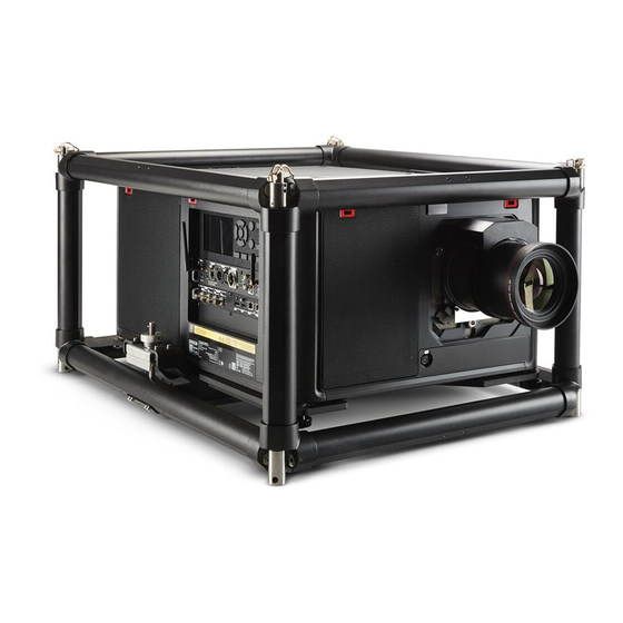
Page 24: Getting To Know The Projector
Getting Started 2.1 Getting to know the projector Orientation convention This manual refers to the left side of the projector as the side at your left hand when standing behind the projector and looking at the projection screen in front of the projector. Image 2-1 Right Left... - Page 25 Getting Started 9 10 11 Image 2-3 IR receiver projector Overvoltage status light rear side USB port (to control Mains power input motorized rigging socket (for C19 plug) frame) Power ON/OFF switch For detailed info about the Input & Communication module see chapter “Input & Communication”, page 39. Projector airflow The projector has three air inlets: one at the top, one at the front and one at the right side of the projector.
-
Page 26: Power On The Projector
Getting Started The RCU will not function properly if strong light strikes the IR sensor window or if there are obstacles between the RCU and the IR sensor. Image 2-5 For detailed info about the RCU see chapter “Pulse Remote Control Unit”, page 31. 2.2 Power on the projector How to power on Does the OVERVOLTAGE status light (reference 1) lit up? -
Page 27: Start Image Projection
Getting Started The start up screen is displayed on the touch panel and when fully started up, it changes to the overview screen. Image 2-8 The background image of the startup screen and info screens can be changed with Projector Toolset with an installed UDM plug-in. - Page 28 Getting Started Image 2-11 The Source selection menu opens on the LCD display. Image 2-12 Use the arrow keys to select the desired source. • the SEL LED (reference 2) of the selected source lit up GREEN, and • the image of the selected source is projected. Image 2-13 Quick test pattern selection Press the Test pattern button (references P) on the remote control or local keypad.
-
Page 29: Switching To Standby
Getting Started Image 2-14 The Test pattern menu opens on the LCD display. Use the arrow keys to select the desired test pattern. 2.4 Switching to standby How to switch to standby Press and hold the Power on/off button for 3 seconds on the local keypad, or press the Power Off button on the remote control. - Page 30 Getting Started Image 2-16: Mains switch Unplug the power cord from the projector. R5911443 /02...
-
Page 31: Pulse Remote Control Unit
Pulse Remote Control Unit Remote control, battery installation ....................32 Remote control, protocol setup ......................33 Remote control, on/off button......................33 Using the RCU ..........................34 Functionality overview........................35 Functions of the “button pressed indicator” ..................35 Function of the RGB filter button ....................36 Displaying and Programming addresses into the RCU..............36 Using the XLR connector of the RCU .....................36 3.10 Using the mini-jack connector of the RCU..................37 3.11 Silicone protection sleeve for the RCU (optional)................37... -
Page 32: Remote Control, Battery Installation
Pulse Remote Control Unit 3.1 Remote control, battery installation Where to find the batteries for the remote control ? The batteries are not placed in the remote control unit to avoid control operation in its package, resulting in a shorter battery life time. At delivery the batteries can be found in a separated bag attached to the remote control unit. -
Page 33: Remote Control, Protocol Setup
Depending on the projector to control the remote control can be switched between these protocols. Which protocol to use • The NEC protocol has to be used for Barco projectors based on the Pulse platform: F70, F80, F90, HDX 4K, UDX, UDM, XDL, etc. •... -
Page 34: Using The Rcu
Using the RCU in combination with a 3D emitter When using a 3D emitter that radiates IR beams (e. g. the optional 3D emitter that Barco provides), the IR beams of the 3D emitter may interfere with the IR communication between projector and the RCU. -
Page 35: Functionality Overview
Pulse Remote Control Unit 3.5 Functionality overview Remote Control Unit buttons Image 3-7 Button pressed indicator Backspace (while entering values) Shutter open XLR connector Shutter close Decimal mark (while entering values) LCD panel on / off Macro button Project OSD on / off Menu back Lens zoom Default value button... -
Page 36: Function Of The Rgb Filter Button
Pulse Remote Control Unit 3.7 Function of the RGB filter button Filtering the color of the projected image By pressing the RGB filter button on the RCU you can place a color filter on the output of the projector. This feature can be useful during the installation and configuration of a multi-projector or multi-channel setup. -
Page 37: Using The Mini-Jack Connector Of The Rcu
(optional) Introduction Barco offers a silicone form fitting protection sleeve for the Pulse RCU. The silicone material keeps it comfortably, non slip and soft touch. All buttons and holes remain accessible. The sleeve is quick and easy installed. For ordering information see Barco website. - Page 38 Pulse Remote Control Unit Image 3-10 Place back side (XLR side) of the RCU into the sleeve and pull the other side of the sleeve over the front side of the RCU. Image 3-11 R5911443 /02...
-
Page 39: Input & Communication
Input & Communication Introduction ..........................40 Local Keypad and LCD panel ......................40 Communication connections......................41 LED and Button indication chart.....................43 Pulse Quad Combo input Mk II ......................44 Pulse Quad Combo input Mk I .......................45 Pulse Quad DP 1.2 input .......................46 Pulse SFP input..........................47 R5911443 /02... -
Page 40: Introduction
Input & Communication 4.1 Introduction General The Input & Communication module consists of a local keypad with LCD panel (1), a communication panel (4) and a Quad Combo input board (5). The free input slot can be used for optional modules (e.g. the Quad DP 1.2 input board). -
Page 41: Communication Connections
Input & Communication Local Keypad The Keypad gives direct access to several functions, in addition to access to the menu system. The keypad has a backlight that can be switched on and off manually. By default the light turns off after 5 minutes. - Page 42 Sub-D connector and an USB connector acting as RS input when connected to an USB input of a PC. You can use the RS232/RS422 input to connect a local PC to your UDM series projector. By this way you can configure and control your projector from your local PC.
-
Page 43: Led And Button Indication Chart
Input & Communication RS422 An EIA serial digital interface standard that specifies the electrical characteristics of balanced (differential) voltage, digital interface circuits. This standard is usable over longer distances than RS-232. This signal governs the asynchronous transmission of computer data at speeds of up to 920,000 bits per second. -
Page 44: Pulse Quad Combo Input Mk Ii
Input & Communication Description Color status LIGHT (Illumination LED) Light source is off No light source detected ORANGE Light source is on in ECO mode GREEN Light source is on in normal mode GREEN-ORANGE Light source is on in CLO mode ERR (error LED) No error RED toggles on/off... -
Page 45: Pulse Quad Combo Input Mk I
Input & Communication HD, 3G & 12G IN 0 OUT 0 IN 1 OUT 1 N.C. HD & 3G IN 0 OUT 0 N.C. IN 1 OUT 1 FPGA IN: HD & 3G SDI IN/OUT OUT 0 OUT: HD, 3G & 12G N.C. -
Page 46: Pulse Quad Dp 1.2 Input
Input & Communication Remark concerning the Mk I and Mk II inputs boards The Mk I input board miss functionality that has been implemented on the Mk II input board. These missing features include: • Loop-through functionality • 12G SDI support •... -
Page 47: Pulse Sfp Input
Input & Communication 4.8 Pulse SFP input The Barco SFP Input Board has been designed and tested to work alongside the Barco SFP Output Board. However, it is possible that the SFP Input board can also work with other third-party devices that support 12G over fiber. - Page 48 Input & Communication R5911443 /02...
-
Page 49: Gui - Introduction
GUI – Introduction Overview .............................50 Navigation............................51 Test Patterns ..........................52 About this chapter This chapter gives an general overview of the Graphic User Interface. R5911443 /02... -
Page 50: Overview
GUI – Introduction 5.1 Overview GUI – Status Screens While the projector menu is not active, or the projector is Ready or Standby mode, the Status screen are visible. These screens give an overview of the state of the projector and can be navigated through using the left and right arrow keys. -
Page 51: Navigation
GUI – Introduction The projector's software platform uses access levels what each user can do. A standard user has access to all projector functionality. A certified service technician has also access to the service menu. This menu is password protected. 5.2 Navigation Navigation via the RCU or local keypad Navigating the OSD can be done using the remote control or the local keypad. -
Page 52: Test Patterns
GUI – Introduction • To enter the value as a direct number, press OK, input the digit(s), and then press OK again to execute and exit cursor mode e.g. OK 79 OK. Within an input field, use the * button as backspace button to remove an entered digit. Use the # button to enter a dot (.). - Page 53 GUI – Introduction To turn the test pattern off, return to the previous menu. R5911443 /02...
- Page 54 GUI – Introduction R5911443 /02...
-
Page 55: Gui - Source
GUI – Source Displaying a single source ......................56 Displaying multiple sources: Stitched layouts ..................56 Connector Settings ........................58 About the Source menu This menu is used to select, review and configure sources into the projector. R5911443 /02... -
Page 56: Displaying A Single Source
GUI – Source 6.1 Displaying a single source About selecting a source Before a source can be projected, the source signal must be connected to the source input(s) of the device and a valid synchronization signal must be available along with the source signal on at least one of the input connectors. - Page 57 GUI – Source Type of layout Description Available connectors Mode Four inputs are required. The Quad DP 1.2 Input: Mono / Active sources are displayed next to stereo • 4x DisplayPort each other. 1 2 3 4 : Quad 1 x 4 Two inputs are required.
-
Page 58: Connector Settings
GUI – Source Image 6-4: Input Selection menu, stitched options 6.3 Connector Settings About Connector Settings The Connector Settings menu allows you to change settings for each input connector of the projector. By default all options for every connector are set to automatic, together with the native Extended Display Identification Data (EDID). - Page 59 GUI – Source Image 6-7: Select source Select the desired connector. The Connector Settings menu for this connector will be displayed. Image 6-8: Example of connector settings for an HDMI connector You can change the following: • To force a limit on the color space, select one of the available color spaces. •...
- Page 60 GUI – Source R5911443 /02...
-
Page 61: Gui - Image
GUI – Image Setting image levels manually......................62 Adjusting the sharpness ........................63 Adjusting the gamma correction.....................64 Setting the desired Gamma type ....................65 Digital Shift & Zoom ........................66 P7 Realcolor ..........................69 Setting the output resolution ......................71 Displaying HDR content – Perceptual Quantizer (PQ)..............72 R5911443 /02... -
Page 62: Setting Image Levels Manually
GUI – Image 7.1 Setting image levels manually Purpose Contrast: Change the contrast of the complete output signal (main and PiP window together) of the projected image. Brightness: Change the brightness of the complete output signal (main and PiP window together) of the projected image. -
Page 63: Adjusting The Sharpness
GUI – Image Image 7-4: Brightness slider If necessary, use the ▲ or ▼ key to select the other image adjustment options. How to set up Saturation Level In the main menu, select Image → Saturation. Image 7-5: Image menu — Saturation Use the ◄... -
Page 64: Adjusting The Gamma Correction
GUI – Image Image 7-7: Effect of sharpness adjust How to adjust In the main menu, select Image → Sharpness. Image 7-8: Image menu — Sharpness Use the ◄ or ► key to change the sharpness until the desired value is reached. Image 7-9: Sharpness slider If necessary, use the ▲... -
Page 65: Setting The Desired Gamma Type
GUI – Image Image 7-10: Advanced menu – Gamma Use the ◄ or ► key to change the gamma value between 1.0 and 2.8 . The default value is 2,2. Tip: The slider can be adjusted with a precision of 0.1. Image 7-11: Gamma slider If necessary, use the ▲... -
Page 66: Digital Shift & Zoom
GUI – Image Image 7-12: Example of the HDR Icon in the status menu. For more info on PQ and HDR, refer to “Displaying HDR content – Perceptual Quantizer (PQ)”, page 72. How to adjust the gamma type? In the main menu, select Image → Gamma type. Image 7-13: Image menu —... - Page 67 GUI – Image If you want to reach a lens shift beyond what is possible with the optical shift, you can also perform a digital lens shift. This digital shift will occur on the DMD, rather than the lens holder. So take into account that this additional shift is minimal and restricted to the limits of the chip used.
- Page 68 GUI – Image Image 7-18: Original Picture, not digitally shifted Image 7-19: Picture shifted horizontally Image 7-20: Picture shifted vertically Digital Shift & Zoom In the main menu, select Image → Digital Zoom Shift. Image 7-21: Image menu, Digital Zoom Shift The Digital Zoom Shift menu is displayed.
-
Page 69: P7 Realcolor
GUI – Image Image 7-22: Digital Zoom Shift menu In order to optimize the digital zoom, enable Digital Zoom. When enabled, you can do the following: • Use the ▲ or ▼ key to zoom the lens in or out. •... - Page 70 GUI – Image Image 7-24: P7 Realcolor menu Select the desired Mode. Choose one of the following custom options: • Custom RGB: 3–point color configuration. In RGB mode, the C, M and Y coordinates will be calculated automatically based on the R, G and B coordinates.
-
Page 71: Setting The Output Resolution
GUI – Image Image 7-26: P7 Realcolor menu Choose one of the pre-defined presets: • Standard: A color standard for all UDX projectors, which may be considered the new native settings for all UDX projectors. Default for UDX. • Native: Projector native color settings. •... -
Page 72: Displaying Hdr Content - Perceptual Quantizer (Pq)
GUI – Image Image 7-28: Advanced menu, Output resolution Tip: The current active output resolution is indicated at the bottom of the selection button. The Output resolution menu is displayed. Image 7-29: Advanced menu — Output resolution Select the desired output resolution. Possible resolutions: •... - Page 73 GUI – Image Image 7-30: Example of the HDR Icon in the status menu. How to properly display HDR content? If your provided HDR content has been mastered with PQ (e.g. HDR10 and Dolby Vision), a few changes can be made in order to project the intended mastering on screen. These changes are necessary because HDR content has been mastered specifically for HDR capable displays that are watched in living rooms.
- Page 74 GUI – Image Alter the HDR boost if necessary. You can modify this value to somewhere between 0.8 and 1.2. R5911443 /02...
-
Page 75: Gui - Installation
GUI – Installation Configuring the lens, optical zoom-focus ..................76 Configuring the lens, shift ......................76 Configuring the lens, Mid position ....................77 Laser ranging ..........................78 Manipulating the rigging frame ......................79 Orientation ...........................80 Warping ............................81 Blending & masking ........................93 Laser illumination ........................100 8.10 Scaling modes.......................... -
Page 76: Configuring The Lens, Optical Zoom-Focus
GUI – Installation 8.1 Configuring the lens, optical zoom-focus What can be done? Once a lens has been installed in the projector, you can fine-tune the projected image. Zoom - Focus In the main menu, select Installation → Lens → Zoom focus. Image 8-1: Lens menu, Focus &... -
Page 77: Configuring The Lens, Mid Position
GUI – Installation Image 8-3: Lens menu, Lens shift The Lens shift menu is displayed. Image 8-4: Lens shift menu Use the ◄ and ► keys to shift the lens (image) in horizontal direction. Use the ▲ and ▼ keys to shift the lens (image) in vertical direction. 8.3 Configuring the lens, Mid position What can be done? The lens can be force back to the center position by selecting MID LENS and confirming. -
Page 78: Laser Ranging
GUI – Installation 8.4 Laser ranging What can be done? When the optional laser range finder is installed on the projector, you can use the laser source to measure the distance between the front of the projector and the surface you are projecting on. This can help you fine-tune the position of the projector. -
Page 79: Manipulating The Rigging Frame
GUI – Installation Image 8-8: Example of projected image during laser ranging session with measurement on screen By default the measurement is in meters. If you want the distance projected in feet, you can change the measurement system in the System settings menu. For more info, refer to “Setting the measurement system”, page 125. -
Page 80: Orientation
GUI – Installation Image 8-10: Frame shift menu Use the ▲ or ▼ button to shift the rigging frame (image) in vertical direction. Use the ◄ or ► button to shift the rigging frame (image) in horizontal direction. Confirm with the OK button. The frame rotation menu is displayed. -
Page 81: Warping
GUI – Installation Image 8-12: Installation menu, Orientation The Orientation menu is displayed. Image 8-13: Orientation menu Use the ▲ or ▼ key to select the desired mounting position and press OK button to activate. Use the ▲ or ▼ key to select the desired projection position and press OK button to activate. 8.7 Warping About warping Image warping is the process of digitally manipulating an image to compensate for the distortion of the screen. -
Page 82: Warping - Screen Size
GUI – Installation Image 8-15 In the Warp menu, click Warp to toggle between On and Off. Image 8-16 Image 8-17 8.7.2 Warping – Screen Size About (Warp) Screen Size adjustment If the used source aspect ratio is different than the projector aspect ratio, e.g. source is 16:9 and projector is 16:10, then black bars will be projected. -
Page 83: Warping - 4 Corners Adjustment
GUI – Installation Image 8-19: Warp Menu, Screen Size The Screen Size menu is displayed. Image 8-20: Screen size Select either Screen width or Screen height. Set the new value to shrink either the width or height of the warp outline so that the outline is equal with the active source. - Page 84 GUI – Installation Image 8-21: 4 corner adjustment How to adjust the image? In the main menu, select Installation → Warp → 4 Corners. Image 8-22: Warp menu, 4 Corners The 4 Corners menu is displayed. Image 8-23: 4 Corners Warping To enable 4 Corners warping, make sure the 4 corners slider is set to On.
-
Page 85: Warping - Bow
GUI – Installation Image 8-25 To set warping on one of the four corners, select one of the four corners and confirm. Set the desired X and Y coordinates for this corner, using the arrow keys, and confirm. Image 8-26 Tip: A red border corner will be projected along with the current image. - Page 86 GUI – Installation Image 8-27: Bow distortion Symmetric bow correction In the main menu, select Installation → Warp → Bow. Image 8-28: Warp menu, Bow To enable Bow correction, make sure the Bow slider is enabled (visible by the blue highlight). To perform a symmetric adjustment , make sure the Symmetric slider is set to On (visible by the blue highlight).
- Page 87 GUI – Installation Image 8-30 Use the arrow keys to select the side of the picture that needs a correction and confirm. Image 8-31: Symmetric Bow correction. Use the arrow keys to adjust the angle and linearity (length) of the vectors. Tip: The angle is adjusted by using the up and down arrow keys.
- Page 88 GUI – Installation Image 8-33 There are now two vectors on each side of the picture that can be adjusted individually. Select the desired slider and confirm. Image 8-34: Right vector of the upper side of the picture. Adjust angle and linearity (length) individually to obtain the correct correction and confirm. Tip: Adjust the angle by using the up and down arrow keys.
-
Page 89: Warping - Warp Files
GUI – Installation Image 8-36: Left vector of the upper side of the picture. When completed, a transformation will occur in a way similar to the following example. Observe that the upper side of the picture now has an asymmetric correction. Image 8-37: Example of an asymmetric bow correction Definition of angle and linearity (length) in the bow warp procedure Image 8-38... - Page 90 GUI – Installation To upload or download warp files you can use Projector Toolset or Prospector tool to upload/download the warp grid in the format of an XML file. Alternatively, you can contact the “file endpoint” directly via the curl program or some other tool that supports http upload.
-
Page 91: Warping - Latency Control In A Multi Projector Setup
GUI – Installation Image 8-42 Click on the on/off button on top to activate the selected warp file. Image 8-43 8.7.6 Warping – Latency control in a multi projector setup Transport latency The added delay in the image processing chain. The value is the number of lines relative to the output resolution. - Page 92 GUI – Installation Image 8-44 Identify the projector with the longest delay. For each projector in the setup, select Installation → Warp in the main menu. Image 8-45: Installation menu, Warp In the Warp menu, select Transport Delay. Image 8-46: Warp menu, Transport delay The Transport menu is displayed.
-
Page 93: Blending & Masking
GUI – Installation 8.8 Blending & masking About Blending & Masking Blending is used in multi channel installation to have a seamless transition between the channels. Image blending gives the appearance of a single view, thus achieving realistic immersion for the majority of wide screen applications. - Page 94 GUI – Installation Image 8-50: Blend & Mask menu To enable blending, put the Enable switch to the right. The color of the switch becomes blue when enabled. To project masking lines on the screen, put the Show lines switch to the right. The color of the switch becomes blue when enabled.
- Page 95 GUI – Installation Example of the use of blending When projecting an image with 2 or more projectors, there is always an small overlap that should be corrected by using the blending function. In order to obtain a satisfying result for the Blend function, the overlap / mask zone are recommended to be at least 10% of the picture width.
-
Page 96: Blend Files
GUI – Installation 8.8.2 Blend Files About custom Blend Files Next to setting your specific Blending configuration in the GUI, you can also upload or download a custom Blend configuration file in png, jpg or tiff format to/from the projector. This is a timesaving option when multiple projectors need an identical blending configuration. -
Page 97: Basic Black Level Adjustment
GUI – Installation 8.8.3 Basic black level adjustment About adjusting the black level The purpose of the black level adjustment is to align the black levels in the overlapped regions with the black levels in the other regions. This is needed because the black levels will be brighter in the blend zones, since multiple projectors will project on the same screen area. -
Page 98: Black Level Files
GUI – Installation Enable the Black level button. If you want a visual aid, enable the Show lines button as well. Move the cursor to the side where the overlapped area occurs (left/right/top/bottom) and press enter. Adjust the level with the arrow keys and press enter when the desired black level zone is reached. enter the black level value with the numeric keys in the remote control. -
Page 99: Rgb Adjustment
GUI – Installation Image 8-62 Click on the Enable slider on top to activate the selected Black Level adjustment file. 8.8.5 RGB adjustment About RGB adjustment The purpose of black level correction is to ensure a uniform black level in multi projector setups. Even when two projectors are of the same type, different projectors will output slightly different colors for black due to minor variations in their optical components. -
Page 100: Laser Illumination
GUI – Installation The RGB Adjustment menu is displayed. Image 8-65: RGB Adjustment menu Select one of the three sliders. Use the left and right arrow keys to modify the gain of the chosen color. Repeat for every slider until the desired result is achieved on screen. 8.9 Laser illumination What can be done? Within a certain percentage, the light output of the light source can be reduced by reducing the laser power. -
Page 101: Scaling Modes
GUI – Installation Image 8-67 If you want CLO mode to be active, click Enable underneath Constant light output. 8.10 Scaling modes About scaling modes While the default mode of projection is to fill the screen while respecting the aspect ratio (fill aspect), it is also possible to stretch the image in a different way. -
Page 102: Projection
GUI – Installation Image 8-68: Installation menu, Scaling The Scaling menu is displayed. Image 8-69: Scaling Menu In the Scaling menu, select the desired scaling mode and confirm. 8.11 3D projection 3D setup The projector is capable of displaying 3D images and movies in active stereoscopic 3D. Setup of a 3D installation requires an advanced understanding of 3D systems, both for the projector as well as for the system the signal source originates from. -
Page 103: Setup Process 3D Projection
GUI – Installation What is Active Stereo? Field sequential 3D (also known as active 3D or “Active Stereo”) is a technique of displaying stereoscopic 3D images. It works by only presenting the image intended for the left eye while blocking the right eye's view, then presenting the right-eye image while blocking the left eye, and repeating this so rapidly that the interruptions do not interfere with the perceived fusion of the two images into a single 3D image. -
Page 104: Choosing The Desired Display Setup
GUI – Installation Fixed Video Timing / Layout mode Color depth Source configuration? cable Active Stereo Standard layout (1x1 2560 x 1600 @120 30 bpp (sequential L/R) layout) Active Stereo 4 Column mode (4x1 960 x 2160 @120 Hz 30 bpp (sequential L/R) layout) Active Stereo... -
Page 105: Emitter Setup
Why change the 3D setup? While Barco can provide a 3D emitter and active shutter glasses as options to this projector, you are also free to use a 3D emitter and active shutter glasses of your own choice. Since glasses and emitter can have various specifications compared to the ones Barco can provide, the 3D setup menu allows you to configure the output image to the specifications of your glasses and emitter. - Page 106 GUI – Installation Image 8-74: 3D setup menu Select the desired the stereo Dark Time. Use the slider to set the desired stereo Sync delay. If it is necessary to invert the stereo sync output, enable the Swap eyes option. If the projected moving 3D content doesn’t look smooth enough, enable the Swap frame pair option to help improve this.
-
Page 107: Gui - Profiles
GUI – Profiles Profiles introduction ........................108 Profiles setup parameters......................108 Enable Profiles ........................... 109 R5911443 /02... -
Page 108: Profiles Introduction
GUI – Profiles 9.1 Profiles introduction About Profiles The Profile function make it possible to store different profiles / projector setups for different use cases, and quickly recall them when needed. This means that there is not necessary to enter a lot of different menus to adjust the projector setup for different user cases. -
Page 109: Enable Profiles
GUI – Profiles Settings Area of interest Installation • Lens parameters, if available (only valid if recalled with same lens) Iris Focus Zoom • Lens shift (Vertical / Horizontal) • Motorized Frame parameters, if connected Rotate Tilt Skew • Shutter position •... - Page 110 GUI – Profiles Image 9-2 Image 9-3: Press OK Enter a suitable name for this profile via the pop up keyboard (arrow keys and OK (✓) to select). End the name entry by selecting the “return” key on the pop up keyboard. Image 9-4: Enter a name for the profile Select the “Assign to preset slot”.
- Page 111 GUI – Profiles Recall a profile. Enter the menu Home / Profile The stored profiles will be visible in the menu. Select the actual profile. Image 9-6 Select the numeric shortcut from the remote control. Edit a profile Enter the menu Home/Profiles/Edit Select the profile to be edited.
- Page 112 GUI – Profiles R5911443 /02...
-
Page 113: Gui - System Settings
GUI – System Settings 10.1 Communication, LAN setup ......................114 10.2 IR control ........................... 118 10.3 Setting a custom projector name....................121 10.4 DMX ............................122 10.5 Front XLR output voltage control....................123 10.6 GSM configuration........................124 10.7 Themes ............................. 125 10.8 Setting the measurement system .................... -
Page 114: Communication, Lan Setup
GUI – System Settings 10.1 Communication, LAN setup About a network connection A network connection can be made via a wired connection or via the optional wireless unit. 10.1.1 Introduction to a Network connection DHCP Dynamic host configuration protocol. DHCP is a communications protocol that lets network administrators manage centrally and automate the assignment of IP addresses in an organization's network. - Page 115 GUI – System Settings Image 10-1: Communication menu, LAN The LAN menu is displayed Image 10-2: LAN menu To enable Automatic, put the switch to the right. The color of the switch becomes blue. An automatic IP is assigned. When connected, it is indicated with the connection symbol and the indication Connected. Select APPLY and click OK.
-
Page 116: Wireless Ip Address Set Up
GUI – System Settings Image 10-4: LAN menu Disable Automatic. Put the switch to the left. The switch becomes gray. Use the ▲ or ▼ key to select Address and press OK button to activate the input box. Use the ▲ or ▼ key to change the selected character. Use the ◄... - Page 117 GUI – System Settings Image 10-6: WiFi menu Put the upper switch to the right to enable the WiFi module. The color of the switch becomes blue. Make sure the second switch is set to the right (automatic). Image 10-7: Automatic assignment Select the Select SSID drop-down menu and select the desired wireless network.
-
Page 118: Ir Control
GUI – System Settings How to manually set up the IP address In the main menu, select System Settings → Communication → WiFi. The WiFi menu is displayed. Disable Automatic. Put the lower switch to the left. The switch becomes gray and the label will read “Manual”. Use the ▲... -
Page 119: Projector Address
The following choices are possible: • Generic IR (address 0) • Barco broadcast IR (address 1) Select APPLY and click OK to apply the changes. 10.2.2 Projector address About individual projector address As more than one projector can be installed in a room, each projector should be separately addressable with an RCU or with a computer using serial communication. -
Page 120: Ir Sensors
GUI – System Settings Image 10-12: IR control menu Select the current projector address and enter a new address. Select APPLY and click OK to apply the changes. From now on the projector will only listen to this new address and to its broadcast address. 10.2.3 IR sensors What can be done? Each IR sensor can be individually disabled or enabled. -
Page 121: Setting A Custom Projector Name
GUI – System Settings Select APPLY and click OK to apply the changes. 10.3 Setting a custom projector name What can be done? The default name of the projector is “Pulse”. However, you can change this name to make it easier to spot in a network with multiple devices or projectors How to set a different Hostname In the main menu, select System Settings →... -
Page 122: Dmx
GUI – System Settings 10.4 DMX About the ways to control the projector via DMX DMX signals can be connected to the DMX In port on the communicator interface when using a standard DMX cable equipped with XLR connector. The DMX out can be used to create a chain of DMX devices. One universe can control up to 512 channels. -
Page 123: Front Xlr Output Voltage Control
GUI – System Settings Image 10-19: DMX menu Choose the desired DMX mode. Choose the desired starting channel. Choose whether or not you want the Auto power-down feature to be enabled. If enabled, determine the time- out. If required, enable Art-Net. If enabled, determine the desired Art-Net Universe and Art-Net channel. If a front XLR connector is available on your projector, you can enable the output voltage on this connector. -
Page 124: Gsm Configuration
GUI – System Settings Image 10-21: DMX menu On the bottom of the DMX menu, Enable the XLR connector. Select the desired Output Voltage. 10.6 GSM configuration Only possible when a GSM module with SIM card is installed in the projector. What can be done ? To configure the projector software with the installed SIM card, a correct PIN code (4digits) must be entered. -
Page 125: Themes
GUI – System Settings Image 10-23: Enter PIN code Enter the 4 digits of the pin code and select APPLY and click OK. 10.7 Themes About Themes Themes are used to apply a predefined functionality to the OSD display. There are two options: light or dark (default). -
Page 126: Lens Features
GUI – System Settings Image 10-25: System settings menu – Units The Units menu is displayed. Image 10-26: Units menu Set the desired Temperature unit and Length unit. 10.9 Lens features What can be done? Some lens features can be disabled once they are correctly aligned so that a misalignment during a show is not possible. -
Page 127: Controlling The Backlight Of The Lcd Display
GUI – System Settings Image 10-28: Lens features menu Depending on the lens type, different functions are available such as: • Focus • Horizontal lens shift • Vertical lens shift • Zoom To enable/disable a feature, click on the slider and drag it to the left to disable the feature or the right to enable the feature. -
Page 128: Reset
GUI – System Settings Image 10-30: Backlight menu Choose the desired setting for the backlights. Select one of the predetermined options, or a custom value. 10.11 Reset What can be done? All settings and values on the projector can be reset to its default values. This can be done for one or more settings separately, or all settings together (factory reset). - Page 129 GUI – System Settings Option Setting Factory setting ImageResolution Output Resolution (if applicable) 4K UHD ImageSource Source files Standard ImageStereo Sync delay 0 µs Swap eye Dark time lowest value available ImageTestPattern Test Pattern Off, none selected ImageWarp Screen size 5120x3200 / 2560x1600 4 corner Warp disabled, no warp...
-
Page 130: Lens Calibration
GUI – System Settings Image 10-32: Reset menu Navigate to the checkbox next to the settings that need to be reset and press OK. Multiple selections are possible. Select RESET and press OK to reset all selected settings. 10.12 Lens Calibration Lens calibration is a time consuming operation. -
Page 131: Flex Brightness
GUI – System Settings • Focus • Zoom The text Calibration in progress will be displayed next to selected function until the calibration is completed. When an error is detected, the message Calibration Error is displayed next to function. 10.13 Flex brightness Overview With the FLEX technology the projector owners can lock the light output to different levels. -
Page 132: Rigging Frame Calibration
GUI – System Settings Image 10-36: Flex menu Choose the desired Light output (in lumens) for which you have a code available. Enter the code via the OSD menu and Select APPLY and click OK. 10.14 Rigging frame Calibration How to calibrate the Rigging frame In the main menu, select System Settings →... -
Page 133: Electronic Convergence
GUI – System Settings 10.15 Electronic Convergence What can be done? The convergence patterns can be used to check the convergence alignment of red, green and blue. If there is a misalignment of at least one 1 pixel, an electronic realignment is possible. Mechanical realignment of the convergence can only be done by a qualified service technician. -
Page 134: Advanced Settings
GUI – System Settings Tip: Press Reset to return all values to the factory settings. Repeat all steps until the desired alignment is achieved. 10.16 Advanced Settings About the Advanced Settings menu The Advanced Settings menu is hidden by default for the regular user. you can only make this visible after entering a Service code with the remote control. -
Page 135: Advanced Settings - Statistics
GUI – System Settings Image 10-44: Maintenance menu, Advanced Settings In the Advanced Settings menu, select Color. Image 10-45: Advanced Settings Menu, Color The Color menu will be displayed. Image 10-46: Color menu Select the desired value to change and confirm. Change the values to the desired position, taking into account the color gamut values. - Page 136 GUI – System Settings Image 10-47: Maintenance menu, Advanced Settings In the Advanced Settings menu, select Statistics. Image 10-48: Advanced Settings menu, Statistics The Statistics will be displayed. Image 10-49: Statistics menu R5911443 /02...
-
Page 137: Gui - Status Menu
GUI – Status menu 11.1 Status menu overview......................... 138 No settings can be modified in the status menu. Its only for consulting. R5911443 /02... -
Page 138: Status Menu Overview
GUI – Status menu 11.1 Status menu overview Status menu While in the main menu, press Status. Image 11-1 Source status Displays active source information Product Displays active product information: • Article number: Projector article / part number • Serial number: Projector serial number •... -
Page 139: Product Maintenance
Product maintenance 12.1 Software update ......................... 140 12.2 Cleaning the lens........................141 12.3 Cleaning the exterior of the projector .................... 142 About this chapter This chapter contains general maintenance procedures. R5911443 /02... -
Page 140: Software Update
Download the latest firmware (format .fw) from Barco's website in the same way as for Projector Toolset. Start Projector Toolset and make a connection with the projector. For more information, see the “Projector Toolset”... -
Page 141: Cleaning The Lens
Power on the projector. Wait until the Power on/off button is either lit white or blue. Download the latest firmware file ( format .fw) from Barco's website. The firmware can be downloaded for free from Barco's website, (URL: http://www.barco.com). Click on myBarco and log in to get access to secured information. -
Page 142: Cleaning The Exterior Of The Projector
Product maintenance Warning: Do not wipe back and forwards across the lens surface as this tends to grind dirt into the coating. Use a dry lens cleaning cloth to remove left liquid or stripes. Polish with small circles. If there are still fingerprints on the surface, wipe them off with lens cleaner together with a clean lens cleaning cloth. -
Page 143: A Specifications
Specifications Specifications for UDM 4K22 ....................... 144 Specifications for UDM 4K15 ....................... 145 Specifications for UDM W22 ......................147 Specifications for UDM W15 ......................149 Specifications SDI inputs......................150 Specifications HDMI inputs......................151 Specifications HDBaseT inputs ....................152 Specifications DisplayPort 1.2 inputs.................... 153 Specifications SFP inputs...................... -
Page 144: Specifications For Udm 4K22
Specifications A.1 Specifications for UDM 4K22 Specifications Projector type 4K UHD 3-chip DLP digital projector Technology 0.9" DMDTM x3 Resolution 3,840 x 2,400 (4K UHD) / 2,560 x 1,600 (native) / 5,120 x 3,200 (processing) Brightness 20,000 (4K UHD) center lumens / 19,000 (4K UHD) ansi lumens* 22,000 ISO lumens* Contrast ratio 2200:1... -
Page 145: Specifications For Udm 4K15
3 years *Note *Brightness levels +/- 10% ** Wifi and GSM options are not available in all countries. Check with your Barco representative for more info. ***at higher altitude light output might be dimmed A.2 Specifications for UDM 4K15 Specifications... - Page 146 Specifications ScenergiX Horizontal and vertical edge blending Lenses TLD+ 0,37; 0,65-0,85; 0,8-1,16; 1,25 -1.6:1 ; 1.5-2.0:1 ; 2.0-2.8:1 ; 2.8- 4.5:1 ; 4.5-7.5:1 ; 7.5-11.5:1 Optical lens shift Vertical between -100% to +130%, depending on lens Horizontal up to +/- 40%, depending on lens Motorized zoom and focus (with lens memory on TLD lenses) Motorized lens shift (with position memory on all lenses) Color correction...
-
Page 147: Specifications For Udm W22
3 years *Note *Brightness levels +/- 10% ** Wifi and GSM options are not available in all countries. Check with your Barco representative for more info. ***at higher altitude light output might be dimmed A.3 Specifications for UDM W22 Specifications... - Page 148 15 Class A and CE EN55032 Class A, Rohs Warranty 3 years Notes *Brightness levels +/- 10% ** Wifi and GSM options are not available in all countries. Check with your Barco representative for more info. ***at higher altitude light output might be dimmed R5911443 /02...
-
Page 149: Specifications For Udm W15
Specifications A.4 Specifications for UDM W15 Specifications Projector type WUXGA 3-chip DLP digital projector Technology 0.98" DMDTM x3 Resolution 1,920 x 1,200 Brightness 14,500 center lumens / 14,000 ansi lumens / 15,000 ISO lumens* Contrast ratio 2200:1 Brightness uniformity Aspect ratio 16:10 ScenergiX Horizontal and vertical edge blending... -
Page 150: Specifications Sdi Inputs
Notes *Brightness levels +/- 10% ** Wifi and GSM options are not available in all countries. Check with your Barco representative for more info. ***at higher altitude light output might be dimmed A.5 Specifications SDI inputs For readability, the video timings listed are summarized. For the full list of video timings, refer to the appendices. -
Page 151: Specifications Hdmi Inputs
Specifications Specification Value For future release • 3D support • Interlaced support • Segmented frame support Video timings Type Port type Format progressive HD-SDI Single link • Up to 1920 x 1080 @24 Hz Quad link • Up to 1920 x 1080 @25 Hz •... -
Page 152: Specifications Hdbaset Inputs
Specifications Specification Value Video timings • Up to 4096 x 2160 @24 Hz • Up to 4096 x 2160 @25 Hz • Up to 4096 x 2160 @30 Hz • Up to 2048 x 1080 @48 Hz • Up to 4096 x 2160 @50 Hz •... -
Page 153: Specifications Displayport 1.2 Inputs
Specifications CAUTION: The HDBaseT inputs can bridge a distance of 100 m but are sensitive to radiated electromagnetic interference: radiated electromagnetic interference (e.g. from GSM or switching inductive or capacitive loads) within the limits of electromagnetic compatibility requirements of 3 V/ m can cause random flashes or temporary loss of the projected image. -
Page 154: Specifications Sfp Inputs
Specifications • 1920 x 1080 @120 Hz • 1920 x 1200 @120 Hz • 2048 x 1080 @120 Hz 4 column mode (4x1 • 960 x 2160 @120 Hz layout) • 960 x 2400 @120 Hz • 1024 x 2160 @60 Hz Active 3D Standard layout (1x1 •... - Page 155 Specifications • Up to 1280 x 720 @25 Hz 3G-SDI Single link 1920 x 1080 @50 Hz and @60 Hz 1920 x 1200 @50 Hz, @59.94 Hz and @60 Hz. 2048 x 1080 @50 Hz and @60 Hz 12G-SDI Single link 3840 x 2160 @50 Hz and @60 Hz 4096 x 2160 @50 Hz and @60 Hz 3840 x 2400 @50 Hz, @59.94 and @60...
- Page 156 Specifications R5911443 /02...
-
Page 157: B Video Timing Tables
Video timing tables Overview video timings ....................... 158 Overview video timings SDI Inputs ....................159 Overview video timings HDMI 2.0 inputs..................160 Overview video timings DisplayPort 1.2 inputs ................162 Overview video timings HDBaseT inputs ..................164 About this chapter This chapter contains the tables with video timings for video interfaces. -
Page 158: Overview Video Timings
B.1 Overview video timings List of compatible signals The following table specifies the video signals that the projector can project. Barco Events projectors supports the signal with “X” in the Compatible signals column. Note: Support for refresh rates 24.00, 30.00, 60.00 Hz automatically includes support of 1/1.001 x those refresh rates. -
Page 159: Overview Video Timings Sdi Inputs
Video timing tables Compatible signal 12G SDI Input on Mk Vertical II Input HDBaseT & refresh rate Resolution HDMI 2.0 3G SDI DisplayPort board & HDMI 1.4 (Hz) Inputs Inputs 1.2 Inputs Fiber Inputs Network Inputs 2048 x 1080 — —... -
Page 160: Overview Video Timings Hdmi 2.0 Inputs
Video timing tables Video timing Vertical refresh rate Type Port Type (active pixels x active (Hz) lines) 1280 x 720 HD-SDI Single Link & Quad Link 1920 x 1080 HD-SDI Single Link & Quad Link 1920 x 1080 HD-SDI Single Link & Quad Link 1920 x 1080 HD-SDI Single Link &... - Page 161 Video timing tables Video timing Vertical refresh rate (Hz) 3D support? (active pixels x active lines) 1280 x720 Frame packing Top – bottom 1280 x 720 Frame packing Top – bottom 1280 x 800 1280 x 960 1280 x1024 1400 x 1050 1600 x 1200 1920 x 1080 Frame packing...
-
Page 162: Overview Video Timings Displayport 1.2 Inputs
Video timing tables B.4 Overview video timings DisplayPort 1.2 inputs Overview The following standard video formats are available for the projector. Note: support for refresh rates 24.00, 30.00, 60.00 Hz automatically includes support of 1/1.001 x those refresh rates Video timing Available layout modes, Vertical refresh rate other than standard... - Page 163 Video timing tables Video timing Available layout modes, Vertical refresh rate other than standard Support for 3D? (active pixels x active (Hz) layout (1 x 1 layout) lines) 1920 x 1080 1920 x 1080 4 Quadrant mode (2 x 2 Active 3D layout) 1920 x 1200...
-
Page 164: Overview Video Timings Hdbaset Inputs
Video timing tables Video timing Available layout modes, Vertical refresh rate other than standard Support for 3D? (active pixels x active (Hz) layout (1 x 1 layout) lines) 4096 x 2160 4096 x 2160 4096 x 2160 4096 x 2160 4096 x 2160 B.5 Overview video timings HDBaseT inputs Overview... - Page 165 Video timing tables Available layout modes, other Video timing Vertical refresh rate (Hz) than standard layout (1 x 1 (active pixels x active lines) layout) 2048 x 1080 2048 x 1080 2048 x 1080 2048 x 1080 2048 x 1080 2048 x 1080 2048 x 2160 2 Column mode (2 x 1 layout)
- Page 166 Video timing tables R5911443 /02...
-
Page 167: C Dmx Chart
DMX chart DMX chart input board positioning ....................168 DMX chart, Basic........................168 DMX chart, Extended........................169 R5911443 /02... -
Page 168: Dmx Chart Input Board Positioning
DMX chart C.1 DMX chart input board positioning About the input boards 6 Input selection ranges are reserved in the DMX chart per input board location (named L1 and L2). With the current version of DMX support, it is important to take into account to keep the input boards in their original slots. -
Page 169: Dmx Chart, Extended
DMX chart Function Value Default Action 136 - 143 Select input 7: Quad DP board Input A (if held for 1 second) 144 - 151 Select input 8: Quad DP board Input B (if held for 1 second) 152 - 159 Select input 9: Quad DP board Input C (if held for 1 second) 160 - 167... - Page 170 DMX chart Function Value Default Actions 128 - 135 Select input 6: Quad SDI input (if held for 1 second) 136 - 143 Select input 7: Quad DP board Input A (if held for 1 second) 144 - 151 Select input 8: Quad DP board Input B (if held for 1 second) 152 - 159 Select input 9: Quad DP board Input C (if held for 1...
- Page 171 DMX chart Function Value Default Actions 64 - 67 Set light source to 20% 68 - 71 Set light source to 15% 72 - 75 Set light source to 10% 76 - 79 Reserved for future functionality 80 - 87 Power on / Light source on (If held for 5 seconds) 88- 95 Power down / Light source off (if held for 5 seconds)
- Page 172 DMX chart R5911443 /02...
-
Page 173: D Wifi & Gsm Compliance Information
WiFi & GSM compliance information Compliance FCC ........................174 Compliance IC..........................174 About this chapter This chapter contains important compliance information related to the WiFi and GSM module. Regulatory information for US and Canada can be accessed in the OSD of the projector. In order access it, select System Settings →... -
Page 174: Compliance Fcc
WiFi & GSM compliance information D.1 Compliance FCC Federal Communication Commission Interference Statement You are cautioned that changes or modifications not expressly approved by the part responsible for compliance could void the user's authority to operate the equipment. This equipment has been tested and found to comply with the limits for a Class A digital device, pursuant to Part 15 of the FCC rules. - Page 175 WiFi & GSM compliance information These limits are designed to provide reasonable protection against harmful interference when the equipment is operated in a commercial environment. This equipment generates, uses, and can radiate radio frequency energy and, if not installed and used in accordance with the instruction manual, may cause harmful interference to radio communications.
- Page 176 WiFi & GSM compliance information R5911443 /02...
-
Page 177: E Environmental Information
Environmental information Disposal information ........................178 Turkey RoHS compliance......................178 China RoHS compliance ......................178 Taiwan RoHS compliance......................180 Contact information........................181 Production address........................181 R5911443 /02... -
Page 178: Disposal Information
Electronic Products” (Also called RoHS of Chinese Mainland), the table below lists the names and contents of toxic and/or hazardous substances that Barco’s product may contain. The RoHS of Chinese Mainland is included in the MCV standard of the Ministry of Information Industry of China, in the section “Limit Requirements of toxic substances in Electronic Information Products”. - Page 179 Chinese Mainland, marked with the Environmental Friendly Use Period (EFUP) logo. The number inside the EFUP logo that Barco uses (please refer to the photo) is based on the “General guidelines of environment-friendly use period of electronic information products”...
-
Page 180: Taiwan Rohs Compliance
Environmental information E.4 Taiwan RoHS compliance 限用物質含有情況標示聲明書 (Declaration of the Presence Condition of the Restricted Substances Marking) 設備名稱: 投影儀, 型號(型式): UDM Equipment name: Projector, Type designation: UDM 限用物質及其化學符號 Restricted substances and its chemical symbols 單元 鉛 汞 鎘 六價鉻 多溴聯苯 多溴二苯醚 Unit Lead Mercu- Cadmi- Hexava-... -
Page 181: Contact Information
Registered office address: President Kennedypark 35, 8500 Kortrijk, Belgium Contact address: Beneluxpark 21, 8500 Kortrijk, Belgium Importers contact information To find your local importer, contact Barco directly or one of Barco's regional offices via the contact information given on Barco's web site, www.barco.com. E.6 Production address... - Page 182 Environmental information R5911443 /02...
-
Page 183: Glossary
Glossary Hazard Distance (HD) is the distance measured from the projection lens at which the intensity or the energy per surface unit becomes lower than the applicable exposure limit on the cornea or on the skin. The light beam is considered (to be) unsafe for exposure if the distance from a person to the light source is less than the HD. Hazard Distance (HD) is the distance measured from the projection lens at which the intensity or the energy per surface unit becomes lower than the applicable exposure limit on the cornea or on the skin. - Page 184 Glossary Internet Protocol, each machine that can connect to the Internet needs a unique IP address. When an organization sets up its computer users with a connection to the Internet, an IP address must be assigned to each machine. Without DHCP, the IP address must be entered manually at each computer and, if computers move to another location in another part of the network, a new IP address must be entered.
-
Page 185: Index
Index Numbers/Symbols CE Certification 20 3D emitter Clean setup 105 Exterior 139 3D projection 102 Filters 139 3D setup 103 Lens 139 Cleaning Exterior 142 Lens 141 Active 3D 102 Communication 39 DMX 41 setup 105 Active Stereo 102 Introduction 40 IR control Address Program... - Page 186 Index DisplayPort 1.2 inputs Specifications 153 Hazard Distance 16, 19 DMX 122 Modifying optics 20 DMX chart 167 Hazardous Chemicals 15 Basic 168 HDBaseT inputs Extended 169 Specifications 152 DMX Chart HDMI inputs Input mapping 168 Specifications 151 DMX input 41 High Brightness precautions 16 DMX interface 41 Hostname 121...
- Page 187 Index Local keypad Introduction 114 Functionality overview 40 XLR connector 123 Pulse RCU 31 Remote Control Unit 31 Maintenance Clean exterior 139 Clean filters 139 Clean lens 139 Quad Combo Mk I Software updated 139 Introduction 45 Masking 93 LED behavior 45 mini-jack Quad Combo Mk II RCU 37...
- Page 188 Index Safety notice 10 Lens adjustment Saturation 62 Calibration 130 Scaling modes 101 Lens features 126 SDI inputs Maintenance 134 Specifications 150 Network 114 Serial communication 42 Reset 128 Service Service 134 Convergence 133 Units Electronic Convergence 133 Distance 125 Temperature 125 Introduction 47 LED behavior 47...
-
Page 189: List Of Tools
List of tools List of tools Clean cotton cloth Clean micro fiber lens cleaning cloth (e.g. Toraysee® cloth(s)) Compressed air Lens cleaner (e.g. ZEISS lens cleaner, Purosol™ or other water based lens cleaner products) R5911443 /02... - Page 190 R5911443 /02 | 2020-02-21 Barco NV | Beneluxpark 21, 8500 Kortrijk, Belgium Registered office: Barco NV | President Kennedypark 35, 8500 Kortrijk, Belgium www.barco.com...
Need help?
Do you have a question about the UDM Series and is the answer not in the manual?
Questions and answers