
Related Manuals for Navitron SFB Series

Summary of Contents for Navitron SFB Series
- Page 1 SFB Series ~ Evacuated Tube Collector Installation Manual 2 Lands End Way OAKHAM Rutland LE15 6RB England...
-
Page 2: Table Of Contents
Tel: 01572 725512 Fax: 01572 724390 Email: sales@navitron.org.uk SFB series Installation Manual All-glass Evacuated Tubular Solar Collector with Heat Pipe Section Contents Page/s Solar Collector - weights and dimensions Transportation and storage Installation Packing Lists 4-11 Assembly of the frame and manifold assembly 3.2.1... -
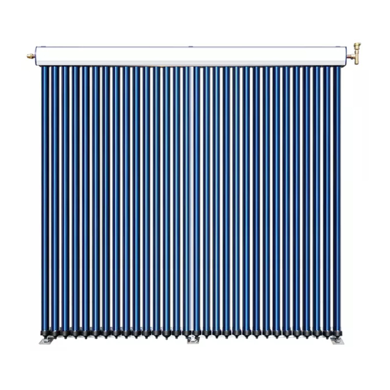
Page 3: Solar Collector - Weights And Dimensions
1.8M 2. Transportation and storage The Navitron Solar Collector is packaged in boxes designed to minimize the risk of damage during transit. Depending on the number of tubes, the collector may be packaged in three or four boxes, one containing the header, frame and various small components, and the others containing the evacuated glass tubes. -
Page 4: Installation
3. Installation 3.1 Packing List Please check that all listed parts for the relevant collector are included before commencing installation SFB104715 Qty. of spare Items Qty.(pcs) Total part SFVB (All-glass Evacuated Tubular Solar Collector with Heat Pipe,Ф47mm*1500mm) Manifold Box Thermal silicon grease(80g) Decoration cover Vertical Bar Aluminum horizontal bar... - Page 5 SFB154715 Qty. of spare Items Qty.(pcs) Total part SFVB (All-glass Evacuated Tubular Solar Collector with Heat Pipe,Ф47mm*1500mm) Manifold Box Thermal silicon grease(80g) Decoration cover Vertical Bar Aluminum horizontal bar Black nylon screw cup Reflectors White Nylon clips for reflectors M8×10(screw, nut, washer) M6×10 (screw+ washer) screw ,washer...
- Page 6 SFB204715 Qty. of spare Items Qty.(pcs) Total part SFVB (All-glass Evacuated Tubular Solar Collector with Heat Pipe,Ф47mm*1500mm) Manifold Box Thermal silicon grease(80g) Decoration cover Vertical Bar Aluminum horizontal bar Black nylon screw cup Reflectors White Nylon clips for reflectors M8×10(screw, nut, washer) M6×10 (screw+ washer) screw ,washer...
- Page 7 SFB304715 Qty. of spare Items Qty.(pcs) Total part SFVB (All-glass Evacuated Tubular Solar Collector with Heat Pipe,Ф47mm*1500mm) Manifold Box Thermal silicon grease(80g) Decoration cover Vertical Bar Aluminum horizontal bar Black nylon screw cup Reflectors White Nylon clips for reflectors M8×10(screw, nut, washer) M6×10 (screw+ washer) screw ,washer...
- Page 8 SFB105818 Qty. of spare Items Qty.(pcs) Total part SFVB (All-glass Evacuated Tubular Solar Collector with Heat Pipe,Ф58mm*1800mm) Manifold Box Thermal silicon grease(80g) Decoration cover Vertical Bar Aluminum horizontal bar Black nylon screw cup Reflectors White Nylon clips for reflectors M8×10(screw, nut, washer) M6×10 (screw+ washer) screw ,washer...
- Page 9 SFB155818 Qty. of spare Items Qty.(pcs) Total part SFVB (All-glass Evacuated Tubular Solar Collector with Heat Pipe,Ф58mm*1800mm) Manifold Box Thermal silicon grease(80g) Decoration cover Vertical Bar Aluminum horizontal bar Black nylon screw cup Reflectors White Nylon clips for reflectors M8×10(screw, nut, washer) M6×10 (screw+ washer) screw ,washer...
- Page 10 SFB205818 Qty. of spare Items Qty.(pcs) Total part SFVB (All-glass Evacuated Tubular Solar Collector with Heat Pipe,Ф58mm*1800mm) Manifold Box Thermal silicon grease(80g) Decoration cover Vertical Bar Aluminum horizontal bar Black nylon screw cup Reflectors White Nylon clips for reflectors M8×10(screw, nut, washer) M6×10 (screw+ washer) screw ,washer...
- Page 11 SFB305818 Qty. of spare Items Qty.(pcs) Total part SFVB (All-glass Evacuated Tubular Solar Collector with Heat Pipe,Ф58mm*1800mm) Manifold Box Thermal silicon grease(80g) Decoration cover Vertical Bar Aluminum horizontal bar Black nylon screw cup Reflectors White Nylon clips for reflectors M8×10(screw, nut, washer) M6×10 (screw+ washer) screw ,washer...
-
Page 12: Assembly Of The Frame And Manifold Assembly
3.2 Assembly of Frames and Manifold 3.2.1 Side Rails: Arrange the 2 side rails as shown below: Fig 3.1... -
Page 13: Fixing The Manifold
3.2.2 Fix the Manifold: Put the manifold between the two turn-ups on all side rails. Fig 3.2 Fix the manifold to the turn-ups on the side rails using screws provided. See the following two pictures. -
Page 14: Fixing The Bottom Rail
Fig 3.4 3.3 Fix the bottom rail: In order to prevent the tube cups from sliding from the rail use the M6x20 screws, nuts and cover with the black caps. Fig 3.5 Fix the bottom rail on the vertical bar using the 2x M8 x10mm screws. Fig 3.6... -
Page 15: Mounting The Solar Collector
Fig 3.7 Fig 3.8 Installation steps: There are a number of alternative methods of fixing Navitron solar collectors to the roof, depending on personal preference and roof structure. Please contact Navitron for further information or installation training. a) Select a suitable location on the roof for the collector. In the northern hemisphere, the collector should ideally face due south, at an angle to the ground equal to the latitude. - Page 16 Fig 3.9 Fig 3.10 Fig 3.11...
-
Page 17: Flat Roof Installation
(big picture for point N) 3.4.2 Flat roof Navitron Ltd supply standing frames for flat roofs and ground mounted systems. Each type of panel requires its own standing frames which are set at an angle of 40 degs. Depending on the location of the standing frame it may be necessary to insert the tubes... -
Page 18: Installation Of The Evacuated Tubes
3.5 Installation of tubes Unscrew the black end cups from the mounting rings, and clip the rings into the bottom rail spacing them out evenly. (See figure 3.14) Fig 3.14 Apply the thermal paste provided liberally to the tip of the copper heat pipes protruding from each evacuated tube. - Page 19 Fig 3.16 Screw the black end cup into the mounting ring and tighten until hand tight. Repeat the process until all the tubes are in place. (See figure 3.16). Fig 3.17 See figure 3.17 for detail of the completed collector.
-
Page 20: Lightning Protection
Fig 3.19 Suggestions: 1. Avoid assembling the panel in direct sunlight. . 2. If the process has to be undertaken in direct sunlight, Navitron Ltd recommends the tubes are covered during the assembly thus preventing thermal tracking within the panel’s collector. -
Page 21: Interconnection Of Multiple Collectors
Please refer to figures 6.1 to 6.3 for some basic variants. If you are unsure or need any further advice please contact the Navitron technical staff at the address and telephone number listed on the cover page... - Page 22 Fig 6.1 Fig 6.2...
-
Page 23: Dimensions Of Pipe Connections
Fig 6.3 7. Pipe Sizing For solar collector arrays up to 5m² (gross collector area), pipe-work of 10mm is • recommended with total pipe length not exceeding 20m. Pipe-work of 15mm may be used but total pipe length should not exceed 10m For solar collector arrays between 5m²... -
Page 24: Precautions
9. Precautions 1. Only temperature sensors (and other electrical accessories) supplied by the controller manufacturer should be connected to the controller. 2. Assembly, installation and maintenance work may only be performed by properly qualified and authorized personnel. 3. The pump station must be installed indoors. 4. -
Page 25: Wind And Snow Loading
angle will enhance winter output. 13. Wind and snow load When installing the collector please consider the issue of wind resistance and the resulting stress on the attachment points. The standard frame is designed to withstand wind speeds of up to 120km/h and 30cm snow accumulation without damage. - Page 26 15. Standing Frame – Flat Roof Kit (FRK) 15.1 Variants The standing frame is designed to attach to the solar panel thus creating an A-frame type arrangement. The kit consists of Legs, Feet, Back Cross supports and Side supports. Each panel has its own type of standing frame; therefore, when ordering please ensure you have identified the correct item.
- Page 27 Attach the legs using the nuts, bolts and washers provided. Note - 3 legs and 4 back cross supports for 30 tube panels. Fit the support 2 feet the standing legs and 2 feet to the bottom side supports of the solar panel frame.
- Page 28 Using the nuts, bolts and washers provided, fit the leg assembly to the collector and attach leg side supports to the panel frame. Note – 3 leg side supports for 30 tube panels.
Need help?
Do you have a question about the SFB Series and is the answer not in the manual?
Questions and answers