Table of Contents
Advertisement
Quick Links
Advertisement
Table of Contents

Related Manuals for Reflex Variomat VS 1


Summary of Contents for Reflex Variomat VS 1
- Page 1 06.07.2016 – Rev. B Variomat 1 Operating manual Original operating manual...
-
Page 3: Table Of Contents
Contents English Variomat 1 06.07.2016 – Rev. B Contents Notes on the operating manual..............................5 Liability and guarantee................................... 5 Safety........................................ 6 Explanation of symbols ..................................6 3.1.1 Symbols and notes used ..............................6 Personnel requirements ..................................7 Personal protective equipment ................................7 Intended use ...................................... - Page 4 Inspection prior to commissioning ..........................62 10.6.3 Inspection intervals ................................. 62 Disassembly ....................................63 Annex ......................................64 12.1 Reflex Customer Service ..................................64 12.2 Conformity and standards ................................. 65 12.3 Certificate No. of the CE type test ..............................66 12.4 Guarantee ......................................
-
Page 5: Notes On The Operating Manual
Reflex Winkelmann GmbH accepts no liability for any damage resulting from failure to observe the information in this operating manual. In addition to the requirements set out in this operating manual, national statutory regulations and provisions in the country of installation must also be complied with (concerning accident prevention, environment protection, safe and professional work practices, etc.). -
Page 6: Safety
Safety Safety Explanation of symbols 3.1.1 Symbols and notes used The following symbols and signal words are used in this operating manual. DANGER • Danger of death and/or serious damage to health • The sign, in combination with the signal word 'Danger', indicates imminent danger; failure to observe the safety information will result in death or severe (irreversible) injuries. -
Page 7: Personnel Requirements
Safety Personnel requirements Only specialist personnel or specifically trained personnel may install and operate the equipment. The electric connections and the wiring of the device must be executed by a specialist in accordance with all applicable national and local regulations. Personal protective equipment When working at the system, wear the stipulated personal equipment such as hearing and eye protection, safety boots, helmet, protective clothing, protective gloves. -
Page 8: Residual Risks
Safety Residual risks This device has been manufactured to the current state of the art. However, some residual risk cannot be excluded. CAUTION Risk of burns on hot surfaces Hot surfaces in heating systems can cause burns to the skin. •... -
Page 9: Description Of The Device
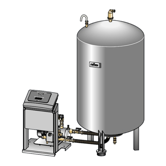
Description The Variomat VS 1 is a pump-controlled pressure maintaining, make-up and degassing station for heating and cooling water systems. The Variomat is essentially a controller with pumps and at least one expansion tank. The expansion tank is fitted with a diaphragm to divide the tank into an air space and a water space. -
Page 10: Identification
4.3.2 Type code Type code (example) Control unit designation Number of pumps Variomat VS 1, VG 500 l, VF 500 l "VG" primary tank 1 2 3 Nominal volume "VF" secondary tank Nominal volume 10 — English... -
Page 11: Function
Description of the device Function Heating system Make-up valve "MAG" pressure expansion tank Pressure sensor Reflex Fillset Impulse, see chapter 4.6 "Optional Overflow valve (motor ball valve) equipment and accessories" on page 13 . Control unit Pump (pressure maintenance) Hydraulic inlets Safety valve •... - Page 12 Description of the device Control unit The control unit contains the hydraulic system and the controller. The "PIS" pressure transducer records the pressure and the "LIS" pressure pick-up registers the level; both values are displayed at the controller. Maintaining pressure The pressure in the system rises when the water is heated.
-
Page 13: Scope Of Delivery
Description of the device Scope of delivery The scope of delivery is described in the shipping document and the content is shown on the packaging. Immediately after receipt of the goods, please check the shipment for completeness and damage. Please notify us immediately of any transport damage. Basic pressurisation equipment: •... -
Page 14: Technical Data
Technical data Technical data Control unit Note! The following values apply for all control units: – Permissible flow temperature: 120 °C – Permissible operating temperature: 70 °C – Permissible ambient temperature: 0 °C – 45 °C Type Power Power supply Degree of Number of RS- Electrical voltage... -
Page 15: Tanks
Technical data Tanks Primary tank Secondary tank Note! Optional heat insulation is available for primary tanks, see chapter 4.6 "Optional equipment and accessories" on page 13 . Type Diameter Ø "D" Weight Connection Height "H" Height "h" (mm) (kg) (inches) (mm) (mm) 6 bar - 200... -
Page 16: Installation
Confirm that installation and start-up have been carried out correctly using the installation, start-up and maintenance certificate. This action is a prerequisite for the making of warranty claims. – Have the Reflex Customer Service carry out commissioning and the annual maintenance. 16 — English Variomat 1 — 06.07.2016 – Rev. B... -
Page 17: Installation Conditions
Installation Installation conditions 6.1.1 Incoming inspection Prior to shipping, this device was carefully inspected and packed. Damages during transport cannot be excluded. Proceed as follows: Upon receipt of the goods, check the shipment for • completeness and • possible transport damage. Document any damage. -
Page 18: Execution
Installation Execution ATTENTION Damage due to improper installation Additional device stresses may arise due to the connection of pipes or system equipment. • Ensure that pipes are connected from the device to the system without stresses being induced. • If necessary, provide support structures for the pipes or equipment. For installation, proceed as follows: •... -
Page 19: Installation Of Add-On Components For The Tanks
Reflex Exvoid with pre-fitted check valve (2) • "LIS" pressure pick-up For add-on components, proceed as follows: 1. Install the Reflex Exvoid (2) at the connection of the corresponding tank. 2. Remove the protective cap from the degassing valve. 3. Use the compression fitting to install the pressure compensation elbow (1) for aeration and ventilation at the tanks. -
Page 20: Tank Installation
Installation 6.3.3 Tank installation ATTENTION Damage due to improper installation Additional device stresses may arise due to the connection of pipes or system equipment. • Ensure that pipes are connected from the device to the system without stresses being induced. •... - Page 21 Installation • Align the primary tank. – The distance of the primary tank to the control unit must match the length of the connection set. • Connect the connection set (2) and (3) with the screw fittings and gaskets to the connections at the lower tank flange of the primary tank.
-
Page 22: Hydraulic Connection
Installation 6.3.4 Hydraulic connection 6.3.4.1 Connection to the facility system CAUTION Hot water vapour can cause burns to skin and eyes. Hot steam can escape from the safety valve. The hot steam will cause scalding of the skin and eyes. •... - Page 23 Primary tank connection set If required, install a diaphragm expansion tank MAG ≥ 35 litres (Reflex N, for example). It reduces the switching frequency and can be also used in the individual protection of the heat generators. According to DIN / EN 12828, the installation of valves between the device and the heat generator is required for heating systems.
- Page 24 Installation "EC" expansion lines Because of the degassing function, you must install two "EC" expansion lines. • One line to the system for the gas-rich water. • One line to the system for the degassed water. The "DN" nominal connection diameter for the "EC" expansion lines must be designed for the "P "...
-
Page 25: Fitting The Thermal Insulation
Use a pressure reducer in the "WC" make-up line if the idle pressure exceeds 6 bar. Note! If you use make-up water from the potable water system, you may need the Reflex Fillset for the "WC" make-up line, see chapter 4.6 "Optional equipment and accessories" on page 13 . -
Page 26: Fitting The Level Sensor
Installation 6.3.6 Fitting the level sensor ATTENTION Damage to the pressure load cell due to unprofessional installation Incorrect installation may result in damage to the "LIS" level sensor, malfunctioning and incorrect measurements from the pressure load cell. • Comply with the instructions regarding the installation of the pressure load cell. The "LIS"... -
Page 27: Switching And Make-Up Variants
Use the Reflex Fillset with integrated system separator when using drinking water for make-up. – If you don't use a Reflex Fillset, you must use an "ST" dirt trap with a mesh size ≥ 0.25 mm for the make-up. Notice! The quality of the make-up water must comply with the applicable standards such as VDI 2035. - Page 28 Installation 6.4.1.2 Using a district heating substation District heating substation Pressure transducer Primary tank Make-up solenoid valve "MAG" pressure expansion tank Dirt trap User-supplied make-up unit Degassing line • For gas-rich water from the system. • For degassed water into the system. Control unit Level sensor Make-up line...
- Page 29 The tank of the heat generator must be fitted with an individual protective device. • When using Reflex Fillsoft softening systems, always install the Fillset Impulse. – The device controller evaluates the make-up quantities and signals a required replacement of the softening cartridges.
-
Page 30: Electrical Connection
Installation Electrical connection DANGER Risk of serious injury or death due to electric shock. If live parts are touched, there is risk of life-threatening injuries. • Ensure that the system is voltage-free before installing the device. • Ensure that the system is secured and cannot be reactivated by other persons. •... -
Page 31: Terminal Diagram
Installation 6.5.1 Terminal diagram "L" fuse for electronics and solenoid valves Digital inputs • Water meter • Insufficient water "N" fuse for solenoid valves Motor ball valve (energy connection) Overflow valve (not for motor ball valve) Pressure analogue input Group message External make-up request Optional for second pressure value Make-up valve... - Page 32 Group message (floating). User, optional N.O. Not assigned External make-up request. Make-up (230 V) • To be used only upon consultation with the Reflex Customer Service. Make-up (230 V) PE shield Level analogue input. Factory prepared, • Display at the controller.
-
Page 33: Rs-485 Interface
• Optional I/O module. Note! If required, please contact the Reflex Customer Service for the protocol of the RS-485 interface, details of the connections and information about the accessories offered. Variomat 1 — 06.07.2016 – Rev. B English — 33... - Page 34 Installation 6.5.2.1 Connecting the RS-485 interface Circuit board of the Control Basic controller. DIP switch 1 Connection terminals for RS-485 connection Proceed as follows: Open the housing cover of the Control Basic controller. Use a screened cable to connect the RS-485 interface to the main circuit board. •...
-
Page 35: Installation And Commissioning Certificate
Installation Installation and commissioning certificate Data shown on the nameplate: Type: Serial number: This device has been installed and commissioned in accordance to the instructions provided in the Operating Manual. The settings in the controller match the local conditions. Note! When any factory-set values of the device are changed, you must enter this information in the Maintenance certificate, see chapter 10.5 "Maintenance certificate "... -
Page 36: Commissioning
This action is a prerequisite for the making of warranty claims. – Have the Reflex Customer Service carry out commissioning and the annual maintenance. Checking the requirements for commissioning The device will be ready for commissioning when the tasks described in the "Installation" chapter have been completed. The system designer or an assigned expert is responsible for carrying out the commissioning. - Page 37 Commissioning Suction pressure maintenance – Device on the suction side of the system's circulating pump Final pressure maintenance • Device on the discharge side of the system's circulating pump The "P " minimum operating pressure is calculated as follows: Calculation Description in metres 0.0 bar...
-
Page 38: Modifying The Controller's Start Routine
Commissioning Modifying the controller's start routine Note! For handling the operator panel see chapter 9.1 "Operator panel" on page 50 The start routine is used to set the required parameters for the device commissioning. It commences with the first activation of the controller and can be run only once. - Page 39 Use the customer menu to repeat the null balancing, see chapter 7.6 "Parametrising the controller in the Customer menu" on page 42. • Contact your Reflex Customer Service, see chapter 12.1 "Reflex Customer Service" on page 64. The start routine restarts.
-
Page 40: Filling The Tanks With Water
Commissioning Filling the tanks with water The following information applies to the devices: • Control unit and primary tank. • Control unit and primary tank and one secondary tank. • Control unit and primary tank and more than one secondary tanks. Facility system System temperature Filling level of primary tank... -
Page 41: Venting The Pump
Commissioning Venting the pump CAUTION Risk of burns Escaping hot medium can cause burns. • Maintain a sufficient distance from the escaping medium. • Wear suitable personal protective equipment (safety gloves and goggles). Vent the "PU" pump as follows: • Remove the vent screw (2) from the pump (1) and vent the pump until bubble-free water escapes. -
Page 42: Parametrising The Controller In The Customer Menu
The "VG" primary tank is empty and the device is installed as per the instructions. If Cancel null balancing null balancing is still not possible, cancel with "Yes".. Contact your Reflex Customer Service. Check the prerequisites for the commissioning, see chapter 7.1 "Checking the requirements for commissioning"... - Page 43 Commissioning Enter the value for the minimum operating pressure. Min.op.pressure 01.8 bar Notice! Calculation of minimum operating pressure, see chapter 7.2 "Determining the P minimum operating pressure for the controller" on page 36 . Switch to the "Degassing" sub-menu. Degassing˃ •...
- Page 44 Commissioning Pre-selected time for a make-up cycle. Upon expiry of this set time, the system interrupts Max. make-up time the make-up and returns the "Make-up time" fault message. 010 min. If the set number of make-up cycles is exceeded within two hours, the system interrupts Max.
- Page 45 Commissioning This value is only displayed if "YES" has been set in the "With softening" menu option. Cap. soft water The attainable soft water capacity is calculated from the type of softening used and the 05000 l specified hardness reduction. •...
-
Page 46: Starting Automatic Mode
If you identify differences to the information provided on the primary tank's 00800 l nameplate, please contact the Reflex Customer Service. This value displays in percent the opening angle of the motor ball valve of the overflow Pos. motor ball valve line. -
Page 47: Operation
Operation Operation Automatic mode After successful commissioning, start the Automatic mode from the device. The Automatic mode is suitable for continuous device operation and the controller monitors the following functions: • Maintain pressure • Compensate expansion volume • Degas • Automatic make-up Press "Auto"... -
Page 48: Manual Mode
Operation Manual mode The Manual mode is intended for test and service tasks. Press "Manual" on the controller. The Auto LED at the operator panel flashes to visually indicate that Manual mode is active. Manual mode enables you to select the following functions and to perform a test run: •... -
Page 49: Summer Operation
Operation Summer operation The degassing of the network water is not necessary if the circulating pumps of the system are shut down during Summer because gas- rich water cannot reach the device. In this event, use the Customer menu to shut down the degassing action to save energy. After Summer, select the "Interval degassing"... -
Page 50: Controller
You can configure the controller settings regardless of the currently selected and active operating mode. 9.2.1 Service menu This menu is protected with a password. It can be accessed only by the Reflex Customer Service. 50 — English Variomat 1 — 06.07.2016 – Rev. B... -
Page 51: Default Settings
Controller 9.2.2 Default settings The device controller is shipped with the following default settings. Use the Customer menu to adjust these values to local conditions. In specific cases, it is possible to further adjust the values in the Service menu. Customer menu Parameter Setting... -
Page 52: Messages
The fault memory stores the last 20 alarms for review, see chapter 7.6 "Parametrising the controller in the Customer menu" on page 42 . Alarm causes can be eliminated by the operator or a specialist workshop. If this is not possible, contact the Reflex Customer Service. - Page 53 Controller ER Code Alarm Floating Causes Remedy Alarm reset contact Pump run time • Set value exceeded. • Check set value in the Customer or Service menu. • Severe water loss in the system. • Check the water loss and correct, if necessary.
- Page 54 • Time interval for replacement of the softening cartridge exceeded. I/O module fault • I/O module defective. Inform Reflex Customer Service. • Connection between option card and controller faulty. • Option card defective. EEPROM defective • EEPROM defective.
-
Page 55: Maintenance
Reset the maintenance counter in the Customer menu. Notice! Maintenance work must be carried out and confirmed by specialist personnel or the Reflex Customer Service, see chapter 10.5 "Maintenance certificate " on page 61 . Variomat 1 — 06.07.2016 – Rev. B... -
Page 56: Maintenance Schedule
Maintenance 10.1 Maintenance schedule The maintenance schedule is a summary of maintenance tasks to be carried out regularly. Maintenance task Conditions Interval ● ▲ = Check, ■ = Service, = Clean Check for leaks. • "PU" pump. ▲ ■ Annually •... -
Page 57: Cleaning The Dirt Trap
Maintenance 10.2 Cleaning the dirt trap CAUTION Risk of injury due to pressurised liquid If installation, removal or maintenance work is not carried out correctly, there is a risk of burns and other injuries at the connection points, if pressurised hot water or hot steam suddenly escapes. •... -
Page 58: Cleaning The Tanks
Maintenance 10.3 Cleaning the tanks CAUTION Risk of injury due to pressurised liquid If installation, removal or maintenance work is not carried out correctly, there is a risk of burns and other injuries at the connection points, if pressurised hot water or hot steam suddenly escapes. •... -
Page 59: Checking Switching Points
Maintenance 10.4 Checking switching points Prerequisite for checking the switching points are the following correct settings: • Minimum operating pressure P , see chapter 7.2 "Determining the P minimum operating pressure for the controller" on page 36 . • Level sensor at the primary tank. Preparation 1. - Page 60 Maintenance Activating the device 11. Switch on the main switch. 12. Activate the make-up. 13. Switch to Automatic mode. – Depending on the filling level and pressure, the "PU" pump and the automatic make-up will be switched on. 14. Slowly open the cap valves upstream of the tanks and secure them against unintended closing. Checking Insufficient water "Off"...
-
Page 61: Maintenance Certificate
Maintenance 10.5 Maintenance certificate All maintenance tasks have been completed according to the Reflex Installation, Operating and Maintenance Manual. Date Service organisation Signature Remarks Variomat 1 — 06.07.2016 – Rev. B English — 61... -
Page 62: Inspection
Recommended maximum inspection intervals for operation in Germany pursuant to Section 16 of the Industrial Safety Regulation [Betriebssicherheitsverordnung] and the vessel classification of the device in diagram 2 of the Directive 2014/68/EC, applicable in strict compliance with the Reflex Installation, Operation and Maintenance Manual. External inspection: No requirement according to Annex 2, Section 4, 5.8. -
Page 63: Disassembly
Disassembly Disassembly DANGER Risk of serious injury or death due to electric shock. If live parts are touched, there is risk of life-threatening injuries. • Ensure that the system is voltage-free before installing the device. • Ensure that the system is secured and cannot be reactivated by other persons. •... -
Page 64: Annex
Annex Annex 12.1 Reflex Customer Service Central customer service Switchboard: Telephone number: +49 (0)2382 7069 - 0 Customer Service extension: +49 (0)2382 7069 - 9505 Fax: +49 (0)2382 7069 - 523 E-mail: service@reflex.de Technical hotline For questions about our products Telephone number: +49 (0)2382 7069-9546 Monday to Friday, 8:00 a.m. -
Page 65: Conformity And Standards
The object of the declaration described above is in conformity with the relevant Union harmonisation legislation - Pressure Equipment Directive Manufacturer 2014/68/EU of the European Parliament and of the Council of 15 May Reflex Winkelmann GmbH 2014. Gersteinstraße 19 D - 59227 Ahlen - Germany Telefon: +49 (0)2382 7069 -0 Ahlen, 19.07.2016... -
Page 66: Certificate No. Of The Ce Type Test
6 bar – 120 °C 07 202 1 403 Z 0621/1/D0045 1000 – 5000 litres 6 bar – 120 °C 07 202 1 403 Z 0013/2/D0045 You will find an up-to-date list under www.reflex.de/zertifikate. Type Certificate number Variomat Giga 1000 – 10,000 litres 6 bar –... - Page 68 Reflex Winkelmann GmbH Gersteinstraße 19 59227 Ahlen, Germany Telephone: +49 (0)2382 7069-0 Fax: +49 (0)2382 7069-588 www.reflex.de...
Need help?
Do you have a question about the Variomat VS 1 and is the answer not in the manual?
Questions and answers