
Related Manuals for Strend Pro WPSR202


Summary of Contents for Strend Pro WPSR202
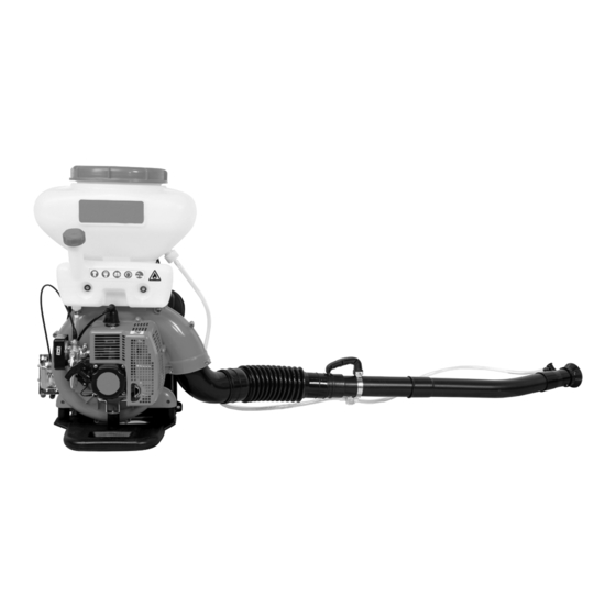
- Page 1 Návod na použitie Rosič s čerpadlom/bez čerpadla Model: WPSR202 Pred použitím zariadenia si pozorne prečítajte návod na použitie. Návod na použitie uschovajte v blízkosti zariadenia pre ďalšie použitie.
- Page 2 Technické parametre Použitie Rosič je prenosné flexibilné a vysoko efektívne zariadenie pre použitie v prevenciu chorôb rastlín a ničenie škodcov v rozsiahlych plantážach, poliach a v ovocných sadoch. Môže byť tiež použitý pre aplikáciu herbicídov, hygienu a prevenciu pred epidémiou, hnojenie a aplikáciu tuhých granúl atď. Hlavné...
- Page 3 Obrázok 2 1.Tesniaca podložka 2.Veko 3.Filtrovacia sieť 4.Hadica 5.Plastová hadica 6.Spodné veko 7.Otvor na vyprázdnenie 8.Postrekovacie veko Vymeniť Obrázok 3 1.Tesniaca podložka 2.Konektor 3.Zátlačné veko Pripojte postrekovaciu tyč k zariadeniu – viď Obrázok 4. Obrázok 4 1.Spona (A) 2.Spona (B) 3.Plastová...
- Page 4 Obrázok 6 1.Svorka (B) 2.Konektor 3.Ohybná rúra 4.Napájacia rúra 5.L-rúra 6.Y-rúra Anti-elektrostatická montáž Postrek alebo rozmetanie granúl môže spôsobiť statickú elektriku na ktorú vplýva mnoho faktorov, ako je napríklad druh chemikálií, teplota vzduchu, vlhkosť vzduchu a pod. Pre vyhnutie sa statickej elektrine používajte priloženú poistnú...
- Page 5 Pridanie chemikálií 1.Počas postrekovania, pri pridávaní chemikálií musí byť vypínač vypnutý Obrázok 8 – viď Obrázok 8. Počas postrekovací regulátor a benzínová páka musia byť v spodnej polohe, v opačnom prípade dôjde k úniku chemikálie. 2.Práškové chemikálie by nemali byť udržiavané v nádrži po dlhú dobu, pretože môže dôjsť...
- Page 6 Rosenie/Postrek 1.Rosenie. Uvoľnite prítlačné veko, nastavte stupeň trysky podľa potreby. Otočte regulátorom pre zmenu množstva rosenia. Viď Obrázok 11. Obrázok 11 Stupeň Výdaj (l/min) 2.Postrek. Množstvo výdaju sa reguluje posúvaním páky v troch polohách. Viď Obrázok 12: Obrázok 12 Bezpečnosť Pozorne si prečítajte návod na použitie.
- Page 7 Štartovanie motora 1. Zabezpečte uzatvorenie ventilu, aby sa predišlo úniku chemikálií počas štartovania motora. 2. Je zakázané stáť pred tryskou počas štartovania. Dokonca aj keď je ventil uzatvorený, môže dôjsť k vyfúknutiu zvyškov z rúry. Rosenie/Postrek 1. Prácu je najvhodnejšie vykonávať počas chladnejšieho počasia s miernym vánkom. Napríklad v skoré ráno, alebo neskôr poobede.
- Page 8 2. Nedostatočný výkon motora Problém Príčina Riešenie Upchatá filtračná doska Vyčistiť Palivo zmiešané s vodou Vymeniť palivo Kompresný pomer a zapaľovanie je v poriadku Prehriaty motor Vypnúť alebo vychladnúť Znečistený výfuk Vyčistiť Konzistencia paliva je nízka Nastaviť karburátor Znečistený kryt valca Vyčistiť...
- Page 9 Údržba 1. Údržba na postrekovacej jednotke - po postrekovaní, vyčistite nádrž na chemikálie. Opláchnite nádrž a všetky ostatné diely. - po rosení, alebo rozmetovaní granúl vyčistite nádrž z vnútra aj z vonku. - po práci uvoľnite veko chemickej nádrže. - po čistení naštartujte zariadenie na nízkej rýchlosti na dobu 2-3 minút. 2.
- Page 10 Schémy zariadenia...
-
Page 13: Technical Specification
Technical specification Name 3WF—3 3WF—3A 3WF—2.6 A 3WF—2.6 Specification Overall dimensions 420×500×690 420×500×800 410×500×755 410×500×645 (mm) Net weight(kg) 11.5 10.5 Capacity of tank(L) 20/26 20/26 Spray ≥4 ≥4 ≥2.3 ≥2.3 Discharge mixture (L/min) rate of chemical Dust ≥6 ≥6 ≥6 ≥6 (kg/min) ≥11... -
Page 14: Main Features
Main Features The main parts of the machine are all made of plastic, so the machine has light weight. The construction design of the machine is unique. The parts contacted with chemical are all made of reinforced plastic or stainless steel, thus it has the property of anti-corrosion and long life in use. - Page 15 Fig.2 1.Sealing washer 2.Lid 3.Filter net 4.Tube 5.Rubber tube 6.Lower Lid 7.Discharge opening 8.Spraying plate Fig.3 1.Sealing washer 2.Connector 3.Pressing lid Connect spraying pipe to the machine as shown in Fig.4. Fig.4 1.Clip(A) 2.Clip(B) 3.Plastic tube 4.Handle 5.Bentpipe 6.Plastic pipe 7.Nozzle 8.Hose 9.Pipe...
- Page 16 2. Assembly for dusting Remove the chemical tank, take down the inlet rubber tube, outlet rubber tube, strainer, spraying lid plate ,pressing lid and union, change for lower lid of chemical tank, then connect the dusting pipe as Fig.5.and Fig.6. Fig.5 1.Cilp 2.Hose 3Union 4.Connecting pipe 5.Dusting pipe Fig.6...
- Page 17 Connect another end conducting wire, then fix conducting wire and insurance chain on bend pipe by screw. Fig.7 Rotation 1. Check 1) Check if there is loose of sparking plug, etc. 2) Check if the air cooling opening is blocked to avoid over-heating during rotation. 3) Check if air filter is dirty to avoid bad rotation and over-waste of fuel caused by quality of incoming gas.
- Page 18 2) As powder chemical can easily become block, so the chemicals should not be in the chemical tank for a long time. 3) While spraying, the chemical tank lid should be turned on tightly. After adding powder chemical, please clean the screw of chemical tank mouth, and then turn on the lid tightly.
- Page 19 speed. Otherwise, the speed. 3) After adjustment is finished, tighten the lock nut. 7. Stopping the engine. 1) During misting operation turn off the chemical first, and then stop the machine. 2) During dusting operation, put the fuel lever and dusting lever at the close position. 3) After finish work, turn off the fuel switch in order to avoid difficult start next time.
- Page 20 Safety 1. Read this manual carefully. Be sure you understand how to operate this machine properly before you use it. 2. Protective clothing (Fig 13) (1)Wear flanged cap. (2)Wear dirt/fog-proof glasses. (3)Wear gauze mask. (4)Wear long gloves. (5)Wear cost guarding against poisons. (6)Wear boots.
- Page 21 though dust gate is closed, residual dust in pipe will be blown out. Shown in Fig 14. 6. Misting/Dusting (1) It is fine to carry out operation during cool weather with little wind. For example: in the early morning or in the late afternoon.
- Page 22 Trouble Cause Remedies Firing device wetted Dry it out Carbon lay down on the Clean the carbon sparking plug The clearance between poles Adjusting the clearance at Spark plug of sparking plug is too big or 0.6—0.7mm too small This insulation of sparking Change sparking plug No flash plug damaged...
- Page 23 2.Engine output is insufficient Trouble Cause Remedies Filter plate clogged wash Compression Fuel mixed with water Change fuel ratio& fire is Engine overheat Shut down or cool it normal Carbon lay down in muffler Clean it Consistency of fuel is too thin Adjust carburetor Carbon lay down on cylinder cover Clean it...
- Page 24 5.Spraying Trouble causes remedies No spray mixture jet or Nozzle switch or Clean it jet intermittently control value clogged Liquid lead pipe Clean it clogged Tighten the tank lid and screw down No pressure or the two wing nuts pressure is lower Spray mixture leakage The spraying lid plate Refit it...
- Page 25 Technical Maintenance and Deposit for a Long Time 1. Technical maintenance on spraying assembly (1) After spraying, clean out any residual spray mixture or dust in the chemical tank. Wash the tank and all other parts. (2) After dusting or granules spreading, clean the dust gate and chemical tank inside and outside.
- Page 26 sparking plug. (3) Screw out the two wing screws. Take off the machine tank. Clean the dust gate and the surface inside and outside of chemical tank. If the residual chemical remains in the dust gate, the dust gate will not properly and the leakage of dust will occur seriously. Then fit the chemical tank on and the loosen the tank lid.
- Page 28 Appendix ⅠList of Engine Parts of Attached Fig.1(Ⅰ) Ser. Ser. Part No. Part Name Part No. Part Name 1E40FP-3Z-7 CYLINDER 1-28 1E40FP-3Z.3-6 WASHER GB/70.1 -M5×20 BOLT 1-29 1E40FP-3Z.3.1 CRANKSHAFT 1E40FP-3Z-6 GASKET 1-31 1E40FP-3Z-16 1E40FP-3Z-18 GASKET 1-32 GB/T859-10 WASHER GB/T97.1-10 1E40FP-3Z-5 GASKET 1-33 WASHER...
- Page 29 Appendix ⅠList of Engine Parts of Attached Fig.1(Ⅱ) Ser. Ser. Part No. Part Name Part No. Part Name 1-54 GB/T9074.4- M5×20 SCREW 1-84 GB/T818- M4×12 SCREW 1-55 1E40FP-3Z.4-1 CASE 1-85 FLOAT 1-56 1E40FP-3Z-17 LABEL 1-86 HINGE 1-58 1E40FP-3Z.4-2 HANDLE 1-87 1-59 1E40FP-3Z-19 RATCHET...
- Page 30 Appendix Ⅱ List of Engine Parts of Attached Fig.2 (Ⅰ) Ser. Ser. Part No. Part Name Part No. Part Name GB/T 6170-M6 2-25 GB/T 9074.4-M5×16 SCREW ASSEM GB/T 93-6 WASHER 2-26 3WF-2.6.3 THROTTLE CABLE GB/T 96.2-6 WASHER 2-29 3WF-3-5 HANDLE 3WF-2.6.10-1 FRAME 2-30...
- Page 31 Appendix Ⅱ List of Engine Parts of Attached Fig.2 (Ⅱ) Ser. Ser. Part No. Part Name Part No. Part Name 2-48 GB/T 896-5 RING 2-70 GB/T 96.2-6 WASHER(NOT USE IN-2.6) 2-49 GB/T 9074.4-M6×20 SCREW ASSEM 2-71 3WF-2.6A.4.2 FANJOINT(NOT USE IN-2.6) 2-50 3WF-3-21 PLUG...
- Page 32 Appendix Ⅱ List of Engine Parts of Attached Fig.2 (Ⅲ) Ser. Ser. Part No. Part Name Part No. Part Name 2-94 3WF-3.17-1 CHEMICAL TANK 2-120 3WF-2.6A.1-3 WASHER(NOT USE IN-2.6) 2-95 BG415-8 CLIP 2-121 3WF-2.6.4-4 PIPE(NOT USEIN-2.6A) 2-97 GB/T818-M5×35 SCREW ASSEM 2-122 3WF-2.6.4-6 L-PIPE(NOT USEIN-2.6A)
- Page 33 Appendix Ⅱ List of Engine Parts of Attached Fig.2 (Ⅳ) Ser. Ser. Part No. Part Name Part No. Part Name 2-145 3WF-2.6.4.1 CONNECTOR 2-146 3WF-2.6.4-2 PIPE 2-147 GB818-M5×25 SCREW ASSEM 2-148 3WF-2.6.4-8 HANDLE 2-149 ZB4-5-4-01 CLAMP 2-150 3WF-2.6.4.3 BLACK NOZZLE 2-151 3WF-2.6.4.3.1 NOZZLE...
- Page 34 Appendix Ⅲ List of Engline Parts Attached Fig .3 (Ⅰ) Ser. Ser. Part No. Part Name Part No. Part Name 3WF-2.6B-2 NELON CLIP 3-23 3WF-3-16 PLATE GB/T6170-M6 3-25 3WF-3.25.4 INSURANDE CHAIN GB/T5356-S=4 GB/T96.2-6 WASHER 3-26 SPANNER S=5 GB/T93-6 WASHER 3-29 3WF-3.26.1A DISASSEMBLY 3WF-3.11...
- Page 35 Appendix Ⅲ List of Engline Parts Attached Fig .3 (Ⅱ) Ser. Ser. Part No. Part Name Part No. Part Name 3-46 GB/T1235-14×3 SEALING WASHER 3-69 3WF-3.16-1 FUEL TANK(NOT USE IN-3A) 3-47 GB/T119-B6×55 3-70 3WF-3.20.1 FIL TERNET ASSEM 3-48 GB/T896-9 RING 3-71 3WF-3-11 SIGN PLA TEPOLLAR...
- Page 36 Appendix Ⅲ List of Engline Parts Attached Fig .3 ( ) Ⅲ Ser. Ser. Part No. Part Name Part No. Part Name 3-92 3WF-3.7-2 DUSTIING PLATE 3-120 3WF-3.19-2 CLAMP PLASTIC TUB (700) 1 3-93 3WF-3.20-1 TUBE 3-121 SG79-10X2 3-94 3WF-2.6A.1-2 PLATE 3-123 3WF-3.19.3.1-2...
- Page 37 Appendix Ⅲ List of Engline Parts Attached Fig .3 ( ) Ⅳ Ser. Ser. Part No. Part Name Part No. Part Name 1E40FC.1 FUEL TANK LID (NOT USE IN-3) 3-153 3WF18-9.03 FUEL TANK LID (NOT USE IN-3) 3-154 1E40FC.1-4 PLASTIC LID (NOT USE IN-3) 3-155 BG328.7-4 FILTER NET(NOT USE IN-3)
-
Page 40: Záručný List
Záručný list Poskytnutá záručná doba (v rokoch): Výrobok: Výrobca: Typ: Podpis a pečiatka predajcu: Výrobné číslo: Modelové číslo: Dátum predaja: Meno zákazníka (názov firmy): Adresa zákazníka (sídlo firmy): Zákazník svojím podpisom potvrdzuje, Podpis zákazníka: že mu bolo zariadenie predvedené a vysvetlené, že bol oboznámený s návodom na obsluhu, nasadením a užívaním stroja a že mu zariadenie bolo vydané... - Page 41 Záznamy o reklamáciách – záručných opravách Podpis prevedenej Dátum Dátum Evidenčné Pečiatka záručnej opravy prijatia ukončenia číslo servisného (Záznam o neoprávnenej reklamácie: reklamácie: reklamácie: technika: reklamácie) Záznamy o servisných prehliadkach Dátum servisnej Meno servisného Pečiatka a podpis prehliadky: technika: servisného technika:...
- Page 42 Podmienky záruky Dodávateľ poskytuje na tento výrobok záručnú dobu uvedenú v tomto záručnom liste za podmienok dodržania spôsobu používania a skladovania výrobku v súlade s platnými podmienkami a normami, ako i návodom na obsluhu. Záručná doba začína plynúť od dátumu predaja. Predĺžená...
Need help?
Do you have a question about the WPSR202 and is the answer not in the manual?
Questions and answers