
Subscribe to Our Youtube Channel
Related Manuals for Robland NZ 3200 AXIS ERGO


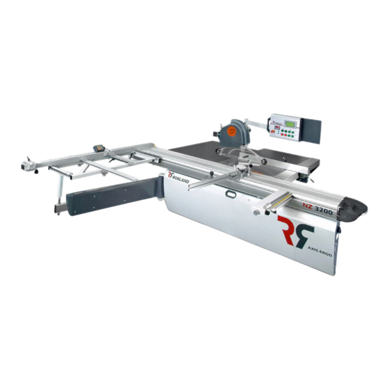
Summary of Contents for Robland NZ 3200 AXIS ERGO
- Page 1 Nouveau Nuevo AXIS - ERGO 3200/3800 Nieuw vέoς Novo HOBO Nuovo www.roblandmachines.com...
- Page 2 U/min 3000 / 4000 / 5000 2270 x 1330 x 1020 + 3250 x 450 x 200 Länge Queranschlag mm 2100 Betriebsspannung Drehstrom V 230 - 400 INFO ROBLAND (teleskopisch bis 3000 mm) Gewicht kg 1050 Technical Specifications Bore mm 30...
- Page 3 Technical features Servo-motor KEB 0,55nm with resolver. Closed-loop-system for a continuous accuracy. Based on a stable aluminium profile. Ball rotation without play. Linear fence without play of 25 mm Accurate servo-drive which guarantees exact functioning Fitted with power choke and an EMC filter to secure insensitivity to hitches User-friendly touch screen.
- Page 4 Composition of the saw blade LUBRICATE N8063 only with TRIBOL 420/220-1 (N8065), to prevent technical problems!!
- Page 5 Assembly ▼ Unwrap the machine (plastic or fibreboard). ▼ Take all accessories of the machine and wait with the AXIS. Take the lever out of its packaging so you can tilt the saw-frame and fasten the nuts ▼ on to the AXIS. ▼...
- Page 6 Assembly sequel ▼ Assemble the upper arm. Fasten the nylon bolts M8-20, this to avoid turning Assemble the upper control: ▼ 2x bolt 912 6 25 2x pinion 125 6 2x thick nut M6 2x plug NID-H6 ▼ Pull the cables ▼...
- Page 7 Assembly sequel ▼ Fit the 2 bottom bolts to the saw guard overhead support arm and attach it parallel to the table ▼ Adjust the touch screen so it is straight ▼ Put the belt of the motor on the right rotational speed and tighten it Turn NAP-8-45 in the service door behind and close ▼...
- Page 8 Assembly sequel ▼ Connect the 2 cables to the servo-motor. (You can‘t make any mistakes fixing the plugs, they can only be fixed in one position). Attach the cables with 3 tie straps. Make sure they can‘t be damaged by the trolley of the fence. Assemble the table extension H1638 (the biggest) First level the supports, regulating bolts M16, to the saw table (+/- 3mm under the table) Fix the table on a par with the saw bench (the side of the sliding table) and adjust the height...
- Page 9 Assembly sequel ▼ Mount the bracket to the saw cap support (bolt 8 90+2x thick pinion + nut M8) ▼ Mount the saw guard with the accessory screws and adjust it so it is flat, with the saw blade in the middle Mount the plastic plugs in the tubes of the saw guard support Fix the 2 supports under the table.
- Page 10 Assembly sequel ▼ Fasten the aluminium cube (Z1230) and push the scale in it ▼ Mount the cross-cut fence on the cross-cut table Fix the Flip-over stops on to the cross-cut fence ▼ ▼ Adjust the roller on the cross-cut table. The roller has to be levelled with the aluminium pro file which holds the cross-cut fence.
- Page 11 Assembly sequel Mount the handle to the sliding table. Make sure the pinion of 0,5mm thickness is fixed between the handle and the lever. ▼ Seal the aluminium ends with the accessory plastic plugs ▼ ▼ Put the machine in place and level it with bolts 2 x M16 x 40 + nut under the sliding table and 2 x M30 (behind the door to change the belt).
- Page 12 Assembly sequel Set up and saw Adjust the measures on the scale to the Flip-stops ▼ ▼ Then follow the touch screen of the AXIS to refer ( → manual AXIS) ▼ Retrieve a couple of measures on the saw blade on the touch screen. Check the measures on the saw blade (with a meter) For example: 1500mm, 1000mm, 500mm, 100mm.
- Page 13 Assembly sequel BAG ASSEMBLY TABLES GENERAL 1 BAG OVERHEAD SAW GUARD 2 4x 912 socket – 10 – 90 Cable protection 600mm 8x 125-10 assembly saw guard 2 plates Z1727 4x thick nut – 10 2x N933 – 8 – 16 (hexagon) 4x 8-12 Nylon bolt 2x N125 –...
- Page 14 A triangle will move the fence within the (1527mm). Push the Robland logo to again with START. warning triangle appears and the safety zone to reach the wanted park.
- Page 15 Setup Sequel Calibration of the fence After pushing MENU, press OFFSET Login password 9876. Confirm with Press ‘OFFSET’ Enter the result of your saw test in ENTER place of 0,0000. Confirm with ENTER Press CAL one time and wait until If the measures are the same, press Do you want to overwrite the Leave the screen by pressing...
- Page 16 Setup Sequel How to use the saw list Password logout. Confirm with The current position is now correct Press MENU ENTER Press the C-list (Saw list) Press the numerical field and enter Press the number of the wanted the wanted measures. position (1).
- Page 17 Setup Sequel How to tilt the aluminium profile Press MENU to put the aluminium Press ALU Press the symbol of the profile Press SAVE to confirm profile horizontally Press ENTER Press ENTER to leave the screen The measure and the profile have changed.
-
Page 18: How To Change The Language
Setup Sequel How to change the language Press MENU Press the flag to change the lan- Pick a language and press ENTER guage to leave the screen... - Page 19 Assembly NZ Axis Ergo Sequel...
- Page 20 Assembly NZ Axis Ergo Sequel...
- Page 21 Assembly NZ Axis Ergo Sequel...
Need help?
Do you have a question about the NZ 3200 AXIS ERGO and is the answer not in the manual?
Questions and answers