Table of Contents
Advertisement
Quick Links
Advertisement
Table of Contents

Related Manuals for Risco RW432M08000A


Summary of Contents for Risco RW432M08000A
- Page 1 LightSYS Air User Manual...
- Page 2 Information in this document is subject to change without notice. Corporate and individual names and data used in examples herein belong to their respective owners. Copyright Information RISCO Group 2023. All rights reserved. No part of this document may be reproduced in any form without prior written permission from the publisher. 12/2023...
-
Page 3: Table Of Contents
DVANCED EATURES FOR YSTEM SERS RISCO C ................... 3 MPOWERED BY THE LOUD Self-Monitoring, Operation and Notification via the RISCO Cloud ........3 iRISCO Smartphone App ......................3 Web User Interface ........................3 ..................6 ONITORING TATION ARTNERSHIP & I .............. - Page 4 Deleting My Own Proximity Tag ..................23 7: D ................24 EFINING OLLOW ESTINATIONS Examples of Follow-Me Notifications ................24 Creating or Editing Follow Me Destinations ..............25 Deleting Follow Me Destinations .................. 25 Testing Follow-Me Destinations ..................26 Keyfob Button for Output Control ................. 26 8: P ..............
- Page 5 Arming/Disarming Modes ..................... 41 Before Arming the System..................... 41 Arming Procedures ......................42 Full ("Away") Arming ....................... 42 Partial ("Stay" or "Home") Arming ..................43 Partition Arming ........................45 Arming All Partitions ......................46 Arming an Individual Partition ..................... 47 Group Arming ..........................
- Page 6 Turning the Inactivity Timer On or Off for the Arming/Disarming Schedule ....... 63 Configuring the UO Option ...................... 64 Turning a UO Schedule On or Off ..................64 Defining the Utility Output(s) for the Schedule ..............64 Setting the Day and Time for the UO Schedule ..............64 Defining a UO Schedule as a "Vacation"...
- Page 7 Panda Keypad Indicators ......................80 Remote Control Indicators .................... 80 4-Button Panda Keyfob Indicators ................... 80 12/2023 Page vi 5IN3047...
-
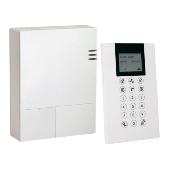
Page 8: Lightsys Air Main Features
A flexible system that is scalable according to your needs, LightSYS Air empowers you to utilize up to 128 zones and 128 system users. LightSYS Air utilizes a wide range of RISCO peripherals in almost any combination – as well as a multitude of other security and safety accessories. - Page 9 Main Panel Indication LEDs Color State Status Green Power OK AC trouble Power LED Orange Battery trouble. System armed (Away or Stay) Rapid flash Alarm System is in exit Slow flash delay Green System ready System in Status LED Exit/Entry delay Slow flash with front door open...
-
Page 10: Empowered By The Risco Cloud
Self-Monitoring, Operation and Notification via the RISCO Cloud Powered by the RISCO Cloud, the iRISCO Smartphone app and Web User Interface empower system users with self-monitoring, notification, control, and operation of their systems remotely - anywhere, anytime, with or without a monitoring station. The RISCO Cloud also enables operating RISCO’s Home Automation services. - Page 11 Capabilities Description Communication GPRS/GSM (2G), GSM (4G), IP/WI-FI modes (modules) Wireless zones Wireless frequencies 868.65 MHz, 433.92 MHz Camera frequency 869.525 MHz, 916 MHz • Security 868.65 MHz, 10 mW Power Output • Camera 869.525 MHz, 100 mW System users (user 128 (includes 1 installer, 1 sub-installer, and 1 Grand Master codes) code)
- Page 12 Supports up to 4 programmable utility outputs (UOs) Programmable utility outputs (UO) Compliance Statement Hereby, RISCO Group declares that the LightSYS Air is designed to comply with: • EN50131-1 • EN50131-3 Grade 2, Environmental Class II • EN50131-6 Type A •...
-
Page 13: Monitoring Station Partnership
EN50136 Compliance: • RISCO has designed the LightSYS Air IP and GSM communication modules to be in compliance with the information security and substitution security requirements of EN50136. Monitoring Station Partnership For extra security monitoring, LightSYS Air can be used with up to 2 separate monitoring stations. - Page 14 Device/interface Description & model numbers Panda 2-Way KeyFob: RW332KF1 Web User Interface iRISCO app for Smartphones (both iOS and Android) SMS notifications (for mobile phones) 12/2023 Page 7 5IN3047...
-
Page 15: Important Safety Precautions
Important Safety Precautions WARNING: Usage of this product that is not in accordance with the intended use and manufacturer instructions can result in damage, injury or death. WARNING: Make sure this product is not accessible by those for whom operation of the system is not intended, such as children. -
Page 16: Initial Setup Tasks For The Grand Master
Step 1: Changing the Default Grand Master Code Step 2: Registering the System to the RISCO Cloud Step 3: Logging into the RISCO Cloud / Web User Interface Step 4: Downloading the iRISCO Smartphone App Step 5: Working with Keypads and User Menus... -
Page 17: Step 1: Changing The Default Grand Master Code
Step 2: Registering the System to the RISCO Cloud Registering to the RISCO Cloud is a one-time procedure that allows you to use the iRISCO Smartphone app and Web User Interface. This procedure should be performed by the system installer, after you supply the installer with the required information, such as an e- mail address. -
Page 18: Viewing The Panel Id At The Keypad
Step 3: Logging into the RISCO Cloud / Web User Interface You must log into the RISCO Cloud after registration. In addition, the Grand Master and other system users (according to user authority level) can access and use the Web User Interface, which offers basic and advanced remote operation, control, and management operations for the system. -
Page 19: Step 5: Working With Keypads And User Menus
Step 5: Working with Keypads and User Menus Keypad Buttons Familiarize yourself with the keypad buttons for Grand Master setup tasks as well as the buttons used for the operational procedures performed by system users. Also see the packaged keypad instructions and the respective procedures in this manual. This describes the main functions of keypad buttons for both Grand Master setup tasks and the operational commands available for all system users. -
Page 20: User Menus
Panda Slim Keypad For Grand Master Setup For User Operations Keypad Buttons PANIC: To activate a panic alarm —— 1 and 2 1 = A GROUP: To select group/s for GROUP: To select group/s for 2 = B —— group group arming 3 = C arming... -
Page 21: Exiting User Menus
Exiting User Menus After you have finished with all the setup tasks, exit from the user menu. ➢ To exit a user menu: • Press the Exit button repeatedly (see table in Keypad Buttons, page 12) to exit all menu options and user menus until INSERT CODE appears. - Page 22 Authority Description of permissions level o Can perform the following for one or more partitions: ▪ Arming and disarming ▪ Bypassing zones ▪ Accessing designated partitions ▪ Viewing system status, trouble, and alarm memory User ▪ Resetting the switched auxiliary output (i.e. for disabling fire alarms) ▪...
-
Page 23: Describing User Codes
Describing User Codes In order to perform system operations and commands, all system users must enter their personal user code at the keypad. Up to 128 different codes are available, to be used for the installer, sub-installer, Grand Master and all other system users. The Grand Master assigns a unique, numeric user code for each system user from a keypad, or via the Web user interface. -
Page 24: Creating Or Editing User Codes
Creating or Editing User Codes ➢ To create or edit a user code from a keypad: If not known, find out from the installer what the code length requirement is for system users. Enter your Grand Master or user code, and then press OK. Scroll to the Codes/Tags menu, and then press OK. - Page 25 ➢ To create or edit a numerical Duress-Disarming code: If not known, find out from the installer which user index number was assigned the "Duress" authority level, as well as the code length requirement. Enter your Grand Master code, and then press OK. Scroll to the Codes/Tags menu, and then press OK.
-
Page 26: Creating Or Editing Labels
Creating or Editing Labels ➢ To create or edit a label: • Using the scroll buttons to move the cursor, at each cursor position enter (or over-write) a character/symbol by pressing the appropriate button (perhaps repeatedly) to cycle through the button's various options, as listed in the table below. Note that after a few seconds the cursor will automatically advance to the next position. -
Page 27: Describing Proximity Tags
Describing Proximity Tags Proximity-enabled RISCO keypads allow using Proximity tags to operate the system (per user authority level – see Describing User Authority Levels, page 14). By holding a personal Proximity tag close to the Proximity sensor of any Proximity-supported keypad, it functions the same as entering a personal user code. -
Page 28: Defining And Enrolling Proximity Tags
Defining and Enrolling Proximity Tags ➢ To define and enroll Proximity tags: Enter your Grand Master code, and then press OK. Scroll to the Codes/Tags menu, and then press OK. At Define press OK. Scroll to the user index number (001—128) for which you will define a Proximity tag – or scroll to Grand Master to define your Proximity tag, and then press OK. -
Page 29: Deleting Proximity Tags
Deleting Proximity Tags Proximity tags can be deleted by the Grand Master, and also by the system user (his/her tag only). The Grand Master can delete Proximity tags (including the Grand Master's) by the following methods: • By index number—if the user's index number is known •... -
Page 30: Deleting A Proximity Tags By Its Tag
Deleting a Proximity Tags by its Tag ➢ To delete a Proximity tag by its tag: Enter your Grand Master code, and then press OK. Scroll to the Codes/Tags menu, and then press OK. Scroll to Delete By Tag, and then press OK. Within 10 seconds, hold the tag about 2 cm (1 inch) directly above the keypad's built-in Proximity sensor;... -
Page 31: Step 7: Defining Follow-Me Destinations
Step 7: Defining Follow-Me Destinations The Grand Master can define up to 64 Follow-Me (FM) destinations ("user-recipients") that will receive notification of system events such as alarm activations: • If system is Cloud-connected (for example if using a Smartphone with the Cloud- connected iRISCO app): a FM user can receive notifications by E-mail, push- notification or SMS-notification simultaneously. -
Page 32: Creating Or Editing Follow Me Destinations
Creating or Editing Follow Me Destinations ➢ To create or edit a FM destination: Enter your Grand Master code, and then press OK. Scroll to the Follow Me menu, and then press OK. At Define press OK Scroll to an available FM index number (01—64) -- or scroll to an existing FM index number that you want to edit, and then press OK. -
Page 33: Testing Follow-Me Destinations
Press and hold down the Exit button (see table in Keypad Buttons, page 12). While pressing it, also press 0. Press OK; the destination (telephone number or E-mail) is deleted. [To delete the label]: Scroll to Label, and then press OK. Scroll to each character to delete, and then press 0 to delete it. -
Page 34: Step 9: Performing A Wi-Fi Scan
Step 9: Performing a Wi-Fi Scan This procedure displays the available networks to connect to. ➢ To perform a Wi-Fi Scan: At the keypad, enter your Grand Master code, and then press OK. At Activities press OK. Scroll to Wi-Fi, and then press OK. Scroll to Wi-Fi Scan, and then press OK;... -
Page 35: Operating The System
Operating the System This chapter contains all the operational procedures available for system users. Modes of Operation The system can be operated by authorized users either remotely or locally (at the premises). Remote Operational Modes • Smartphones via the iRISCO app (see the app for instructions) •... -
Page 36: Operating Remotely By Sms
Operating Remotely by SMS You can operate the system remotely by sending SMS commands. NOTES: • To utilize SMS a GSM module must be installed – ask your installer. • Commands entered are not case sensitive (upper and/or lower case are ok). •... -
Page 37: Operating Locally By Keypads, Remote Controls/Keyfobs, And Proximity
Operating Locally by Keypads, Remote Controls/Keyfobs, and Proximity Working with Keypads Step 5: Working with For a description of keypad buttons used for user operations, see Keypads and User Menus , page 12. Keypad Display Options Using the "Multi View" Keypad Display The keypad displays each partition number, with date, and time. -
Page 38: Using The "Blank" Keypad Display
Using the "Blank" Keypad Display If installer-defined, two minutes after the last keypad operation the keypad display will appear blank, other than the text "ENTER CODE." This feature prevents the system status from displaying for unintended viewers – for example, from keypads that are located outside the premises. -
Page 39: Obtaining System Status - Requested From Remote Controls
Information Types of information that can be received: requested from: • Keypad display indicators (icons and/or text) LightSYS Air Panda Keypad • Keypad beeps (arming/disarming, entry/exit countdown) • Single siren "squawk" for arming confirmation only • Keypad's LEDs Slim keypad •... -
Page 40: Obtaining System Information - Requested From, And Viewed At Keypads
Obtaining System Information – Requested from, and Viewed at Keypads The following system information is viewed only – on keypad displays (not relevant for the Slim keypad): • Event Log • System Troubles • Alarm Memory • Partition Status • Zone Status •... -
Page 41: Viewing System Troubles
Viewing System Troubles A flashing power icon ( ) on the keypad indicates there are current troubles in the system that you can view. ➢ To view all system troubles: At the keypad, enter your Grand Master or user code, and then press OK. Scroll, to View and then press OK. -
Page 42: Viewing Zone Status
Viewing Zone Status View the status of all zones in the system. ➢ To view zone status: At the keypad, enter your Grand Master or user code, and then press OK. Scroll, to View and then press OK. Scroll to Zone Status and then press OK. Scroll through the zones to view their current status. -
Page 43: Serial Number
Serial Number ➢ To view the main panel serial number: At the keypad enter your Grand Master or user code, and then press OK. Scroll to View and then press OK. Scroll to Service Information and then press OK. Scroll to Serial Number and then press OK, the main panel's 11-digit serial number displays. -
Page 44: Cloud Status
Cloud Status View the status of the Cloud. ➢ To view Cloud status: At the keypad, enter your Grand Master or user code, and then press OK. Scroll, to View and then press OK. Scroll to Cloud Status and then press OK. View the Cloud Status, which will display as Connected or Disconnected. -
Page 45: Bypassing Zones
Bypassing Zones If installer-enabled, you can arm a partition – even if a zone within that partition is not secured – by manually bypassing that zone. If not bypassed, when a zone is not secured, or "open" (OP) for whatever reason, by default it will be in a "not-ready"... -
Page 46: Defining Zone Bypass Status
Defining Zone Bypass Status If installer-configured, you can perform either the following procedure to bypass zones, or the quick procedure for one-time-only bypassing (see Quickly Bypassing/Un-Bypassing Zones on a One-Time Basis, page 40). ➢ To define a zone's bypass status: At the keypad, enter your Grand Master or user code, and then press OK. -
Page 47: Quickly Bypassing/Un-Bypassing Zones On A One-Time Basis
Bypass Option Procedure: a. At the One-Time-Only option, press OK. b. Scroll through the zones to one for which you want to One-Time-Only change its bypass status. c. Toggle to either Y (to bypass) or N (to un-bypass), and then press OK. a. -
Page 48: Arming & Disarming The System
Arming & Disarming the System System arming protects the premises by triggering alarms and sending notifications upon detection from any installed detector. System users can arm/disarm the system according to their user authority level. Arming/Disarming Modes LightSYS Air offers the following modes of arming/disarming the system: Arming Modes ✓... -
Page 49: Arming Procedures
• Check for system troubles. It is good practice to scroll through and view all troubles, whether or not your system is configured to require viewing them before arming. CAUTION: Depending on the system configuration, you may be able to arm the system while bypassing all (or specific) open zones, and/or arm while overriding system troubles, however, depending on the circumstances these arrangements may compromise the level of protection that the system offers. -
Page 50: Partial ("Stay" Or "Home") Arming
Device Full-Arming procedure: ❖ Quick Arm mode: Press ❖ High Security mode: Enter code ➢ press ❖ Proximity mode: Place Proximity tag ❖ Quick Arm mode: Press ❖ High security mode: Press ➢ enter code ❖ Proximity mode: Press ➢ place Proximity tag NOTE: If needed, press to "wake-up"... - Page 51 Perform the following arming procedure in the table below. NOTES: • If you enter your code incorrectly, three short beeps will sound. Re-enter the code. • Keyfob and remote control buttons can have different functions and are installer-defined. • Proximity arming is installer-defined, and can vary per system user. Device Partial-Arming procedure: ❖...
-
Page 52: Partition Arming
Partition Arming Each partition in the system (32 maximum) is a separate entity, whereas it can be independently armed/disarmed (fully or partially) by those users with the appropriate authority level – regardless of the state of the other partitions in the system. Each zone (detector) of any type is associated with (assignable to) one or more partitions. -
Page 53: Arming All Partitions
Arming All Partitions Arm all partitions at the same time, as either fully-armed or partially-armed. ➢ To arm all partitions: Verify that the areas of the premises to be armed are vacated, and that the system is ready to be armed (view the READY indicator). If not ready to arm, secure (or bypass) any open zones, see Bypassing Zones (Arming with Manually-Bypassed Zones), page 51 and also Forced Arming (Arming with Automatically- Bypassed Zones), page 50. -
Page 54: Arming An Individual Partition
For this: Do this to arm ALL partitions: ❖ Quick mode: Press Arming an Individual Partition Arm an individual partition, as either fully-armed or partially-armed. For multiple partitions, repeat this procedure as needed. ➢ To arm an individual partition: Verify that the areas of the premises to be armed are vacated, and that the system is ready to be armed (view the READY indicator). -
Page 55: Group Arming
For this: Do this to arm an INDIVIDUAL partition: ❖ Quick mode: Press partition number (1—3) ➢ press (full-arm) or (partial-arm). ❖ High security mode: Press partition number (1—3) ➢ press (partial-arm). ➢ enter code (full-arm) or ❖ Proximity arming: Press partition number (1—3) ➢ press (partial-arm) ➢... - Page 56 For this: Do this to GROUP arm: ❖ If user has permission for 1 partition: Press the group to arm (A, B, C, or D) key for 2 seconds. To arm another group for this single partition, repeat this procedure. ❖...
-
Page 57: Automatic Arming And Disarming
Automatic Arming and Disarming You can have the system arm and disarm automatically for re-occurring weekly schedules, one-time schedules, and vacation schedules (see Defining Automatically-Operated UOs and Arming Operations, page 61). Arming with System Troubles If installer-configured, you can arm the system while overriding all current troubles, provided you first view and confirm all the troubles. -
Page 58: Bypassing Zones (Arming With Manually-Bypassed Zones)
Bypassing Zones (Arming with Manually-Bypassed Zones) See Defining Zone Bypass Status, page 39 and Quickly Bypassing/Un-Bypassing Zones on a One- Time Basis, page 40. Keyswitch Arming If the system is equipped with a keyswitch, perform arm and disarm operations by "toggling"... -
Page 59: Disarming All Partitions
Disarming All Partitions You can disarm all fully-armed or partly-armed partitions at the same time (per your user authority level – "all" refers to the maximum partitions a user's authority level enables him/her to operate) – which may not necessarily be all the partitions in the system. ➢... -
Page 60: Duress Disarming
For this: Do this to disarm an INDIVIDUAL partition: ❖ Disarm an individual partition: Enter code ➢ press disarm button ➢ enter the 2-digit partition number (example 03) ➢ press disarm button. ❖ Proximity disarm: Place tag ➢ enter the 2-digit partition number (example 03) ➢... -
Page 61: Returning The System To Normal Operation After Alarm Activation
CAUTION: During or after any type of alarm activation (manual or automatic), before approaching or entering the premises, first be certain that there is no danger present. You may need to contact responding agencies (police, fire, etc.) in order to confirm whether it is safe to return to the premises. -
Page 62: Resetting The System With Installer/Technician Intervention
Resetting the System with Installer/Technician Intervention The following methods of resetting the system require installer/technician intervention (note that a system user must contact the installer/technician after each alarm activation): • Anti-Code reset (also known as "Technician reset") • Configuration Software reset Anti-Code Reset (Technician Reset) If installer-enabled, upon alarm activation the system will not be ready to arm until the technician/installer provides you with a code that allows you to reset the system. -
Page 63: Disabling Smoke/Heat Detectors After Alarm Activation
At Activities press OK. Scroll to Config SW, and then press OK; either CS CONNECT or ENABLE CS displays: • [If ENABLE CS displays]: The system is not currently configured to allow the technician/installer to access the CS. For you to authorize the technician/installer a one-time access to the CS, press OK, scroll to CS Connect, and then proceed to step •... -
Page 64: Activating Emergency Alarms
Auxiliary / emergency alarm • Duress-Disarming alarm NOTE: RISCO Panda keyfobs can also be used to also activate Panic alarms – ask your installer. Upon alarm activation, monitoring station(s) can be automatically notified, which in turn contact responding agencies (fire, police, etc.). See Compliance Statement. -
Page 65: Activating An Auxiliary ("Emergency") Alarm
Activating an Auxiliary ("Emergency") Alarm Keypad: Press this: Panda keypad Buttons 7 and 9 Slim Buttons 5 and 6 Activating a Duress-Disarming Alarm Activated from keypads only, a Duress-Disarming alarm can be activated by all system users during a "duress" emergency situation (typically, where a user is forced to disarm the system against their will). -
Page 66: Describing Utility Outputs
Describing Utility Outputs The system supports up to 4 programmable utility outputs (UOs) in the system. UOs typically automatically activate external devices and appliances such as lighting and air conditioning, or system arming/disarming – in response to installer-defined activation criteria, such as events and other triggers related to alarms, zones, partitions, system events, user actions, and scheduled operations. -
Page 67: Manually Operating Utility Outputs
Manually Operating Utility Outputs NOTES: • All UOs are installer-configured • Proximity and keyfobs/remote controls can be used if installer-configured Device Manual UO activation procedure: ❖ Press Exit button ➢ enter code and press OK ➢ scroll to Activities menu and press OK ➢... -
Page 68: Defining Automatically-Operated Uos And Arming Operations
Defining Automatically-Operated UOs and Arming Operations The Grand Master can configure the following automated system operations according to schedules and other criteria that the Grand Master defines: • One-time system arming/disarming: (For arming within the next 24 hours • Re-occurring weekly schedules: Up to 64, for arming/disarming the system and/or activating/deactivating up to 4 UOs •... -
Page 69: Defining Weekly Schedules For Automatic Arming And Uos
Defining Weekly Schedules for Automatic Arming and UOs You can define up to 64 re-occurring weekly schedules for automatic UO activation/deactivation and automatic system arming/disarming. Each schedule can have up to 2 separate start and stop time intervals per day. For an automatic arming/disarming, you can also set a "user limitation"... -
Page 70: Selecting An Arming Mode For The Arming/Disarming Schedule
Configuring the Arm/Disarm Option Selecting an Arming Mode for the Arming/Disarming Schedule Scroll to 3)ARMING MODE, and then press OK. Scroll to an arming mode: ARM (full arming), STAY (partial arming), or GROUP (group arming), and then press OK. [For Group mode]: Select the group letter(s) to automatically arm (each selected group displays as Y). -
Page 71: Configuring The Uo Option
Configuring the UO Option Turning a UO Schedule On or Off Scroll to 1)ON/OFF, and then press OK. Toggle to ON or OFF to turn the UO schedule on or off respectively, and then press Defining the Utility Output(s) for the Schedule Scroll to 2)UTIL OUTPUTS, and then press OK. -
Page 72: Configuring The User Limitation Option
Configuring the User Limitation Option You can apply a "user limitation" mechanism to prevent selected users from disarming the system during 1 or 2 specified time intervals per day. By default users do not have a user limitation applied. Applying/Removing a User Limitation Scroll to 3)USER LIMIT, and then press OK. -
Page 73: Setting Dates/Times And Activating A Vacation Schedule
Setting Dates/Times and Activating a Vacation Schedule This procedure is for both UO vacation schedules and arming vacation schedules. ➢ To set the date/time and activate an UO or arming vacation schedule: 15. [For a UO vacation schedule only]: First perform the following procedure: Defining a UO Schedule as a "Vacation"... -
Page 74: Using Macros
Using Macros System users can activate macros, which are custom commands for controlling and operating the system. Up to four macros (A, B, C, D) can be recorded (programmed) locally using any RISCO keypad except Slim models. Recording Macros ➢... -
Page 75: Performing Maintenance Tasks
Performing Maintenance Tasks Defining the Time and Date Manually For systems connected to the Cloud, the time and date are updated automatically, however, regardless whether your system is Cloud-connected or not, the time and date can be manually set as needed. ➢... -
Page 76: Performing Sim Card Maintenance
Performing SIM Card Maintenance Checking the SIM Credit Level Receive information on the available credit level of the prepaid SIM card via SMS (installer- configured). ➢ To check the SIM credit level: At the keypad, enter your Grand Master code, and then press OK. At Activities press OK. -
Page 77: Enabling / Disabling The Current Keypad's Chime
Enabling / Disabling the Current Keypad's Chime ➢ To enable/disable the internal chime of the currently-used keypad: At the keypad, enter your Grand Master or user code, and then press OK. At Activities press OK. Scroll to Keypad Sound, and then press OK. At Chime press OK. -
Page 78: Terminating Follow-Me Notifications
Terminating Follow-Me Notifications You can terminate the transmission of FM notifications to the recipients – for example, for a false alarm, where you don’t want the recipients to get notified. ➢ To terminate Follow Me notifications: At the keypad, enter your Grand Master code, and then press OK. Scroll to Follow Me and then press OK. -
Page 79: Performing A Walk Test
Performing a Walk Test A walk test checks the detection ability of all detectors (PIR and Magnetic Contact detectors) in all zones, to ensure correct operation. Test results are displayed on the keypad. A walk test can be a relatively a quick procedure, depending on the scope of the installation and premises, however if needed, up to 60 minutes is allotted for the test. -
Page 80: Testing Follow-Me Destinations
Testing Follow-Me Destinations This tests if notifications sent to Follow-Me destinations (recipients) are received. It is highly recommended to test every FM destination. ➢ To test a FM destination: At the keypad, enter your Grand Master code, and then press OK. Scroll to Follow Me and then press OK. -
Page 81: Performing A Strobe Test
Performing a Strobe Test This tests a siren's strobe light. ➢ To perform a strobe test: At the keypad, enter your Grand Master code, and then press OK. Scroll to Maintenance and then press OK. Scroll to Strobe Test and then select the strobe to test. Press OK;... -
Page 82: Appendix A: Scheduling Chart For Automatic Uo & Arming Operations
Appendix A: Scheduling Chart for Automatic UO & Arming Operations You can use this chart (optional) to list the details of an automatic UO or arming schedule – it can be used for reoccurring weekly schedules, or weekly vacation schedules. Schedule name / number: ______________ Reoccurring weekly schedule: ... -
Page 83: Appendix B: User Menu Maps
Appendix B: User Menu Maps The following user menus and respective options will display according to the system installation, as well as the authority level of the user. User menu Menu options and respective settings Bypass ➢ Zones ➢ Time Only, Bypass Reset, Bypass Recall, Permanent Bypass o Output control ➢... -
Page 84: Appendix C: System Indicators
Appendix C: System Indicators Various audible (sound) indicators and visual (viewed) indicators are available, depending on the system configuration. Sound Indicators Sound indications are available for system status, operations and events: • Beeps and squawks Sound indicators are requested / initiated from keypads and remote controls, and the sounds can be heard from the keypads, remote controls and external sirens. - Page 85 Requested / initiated from: Slim keypad Arming / disarming 1 long beep Armed = 1 squawk Disarmed = 2 squawks (or 4 if disarmed after an alarm) Requested / initiated from Panda keypad Operation / event Sounds from keypad Sounds from siren Intrusion alarm Fast beeping Siren sound (fast beeping)
-
Page 86: Viewed Indicators
Viewed Indicators Requested/initiated from the keypads and remote controls, the following viewed indicators are provided for system status, operations and events: • Texts and messages on keypad displays • Icon status indicators on keypad displays • LED status indicators on keypads and 8-button remote controls For the procedures to view system status, see Obtaining System Information, page 31. - Page 87 If the LED changes to orange, it indicates the remote control battery is low. UKCA and CE RED Compliance Statement Hereby, RISCO Group declares that this equipment is in compliance with the essential requirements of the UKCA Radio Equipment Regulations 2017 and CE Directive 2014/53/EU.
- Page 88 RISCO, for a period of (i) 24 months from the date of connection to the RISCO Cloud (for cloud connected products) or (ii) 24 months from production (for other products which are non-cloud connected), as the case may be (each, the “Product Warranty...
- Page 89 Consequently RISCO shall have no liability for any personal injury, property damage or loss based on a claim that the product fails to give warning.
- Page 90 Contacting RISCO Group RISCO Group is committed to customer service and product support. You can contact us through our website (www.riscogroup.com) or at the following RISCO branches: Belgium (Benelux) Israel United Kingdom Tel: +32-2522-7622 Tel: +972-3-963-7777 Tel: +44-(0)-161-655-5500 support-be@riscogroup.com support@riscogroup.com support-uk@riscogroup.com...
Need help?
Do you have a question about the RW432M08000A and is the answer not in the manual?
Questions and answers