Advertisement
UltraBeam
T roubleshooting
G uide
v .1.1
TROUBLESHOOTING ULTRABEAM
This brief appendix is an indispensable aid in the troubleshooting of your UltraBeam
antenna.
In case of some erratic or unusual behavior PLEASE take a thoughtfully reading of the
following. In many cases an appropriate procedure can lead to an exhaustive solution.
Only on reception of your first test-results and all collected data, UltraBeam c can proceed
to the identification of the problem and, if necessary, replace any faulty component. For a
promptly solution UltraBeam need your help and your understanding of the basics of how
the antenna works. If you supply inaccurate information and/or confused description of the
problem, UltraBeam Technical Department will not be able to provide the optimal support it
is committed to.
Please take your time and read these few pages.
HIGH SWR
Your antenna is build to work on any band (with the exception of 6 meter-band) with a 50
Ohm at the feeding point and a resulting a SWR of 1.1.
Any higher SWR value has to be considered as a malfunction. Possible reasons are:
1) One or more elements (copper-beryllium tape) do not extend to the correct length.
95% of trouble belongs to this point.
2) The feeding line (coax-cable), connector or the antenna switch present some anomaly.
3) The faulty balun inside the driven- element.
When suddenly the SWR figure move from the usual value DO NOT try to vary the length
of a single element or change band continuously.
One of the basic knowledge you have to have is that the, once installed, the value of the
SWR of UltraBeam should never change. A little variation can only happen when the
elements are wet as during a storm. In the 95% the above described conditions should
lead us to point 1.
VISUAL INSPECTION
UltraBeam antennas use transparent fiberglass elements. This trick permits a prompt
visual inspection. The adoption of this material permits a prompt visual inspection and you
can verify, from distance, if the entire motorized Copper-Beryllium tape moves correctly
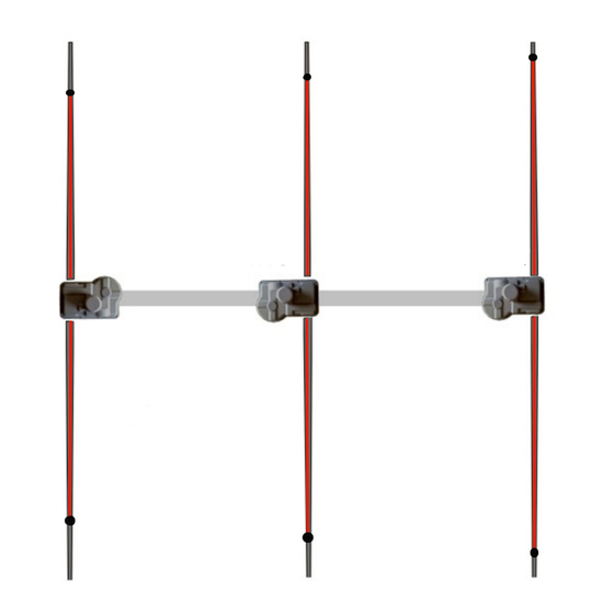
inside the elements. Picture (pic.1) represents a sketch of a 6-20 3-Elements Yagi.
First of all you have to observe the movement of the Copper-Beryllium tape inside the
glass fiber elements during a band change.
With the controller switched to 20mt. and on the NORMAL direction, look whether the ends
of the elements match with pic.1. Now switch to 10mt. and carefully inspect if the ends of
the elements position match with pic.2.
The two positions have to be as in pic1 and pic2. Memorize the 20mt, move to a different
band and then return on 20mt. If the positions are the same as before you can exclude
any fault in each motor-unit and in the Antenna Controller.
A "CALIBRATE " command from Antenna Controller menu will fix any further problems.
If the elements don't reach the right position or produce a loud noise after a band change,
don't try any further attempt to adjust by using the Antenna Controller.
1
Advertisement
Table of Contents

Related Manuals for WiMo ULTRABEAM


Summary of Contents for WiMo ULTRABEAM
- Page 1 In many cases an appropriate procedure can lead to an exhaustive solution. Only on reception of your first test-results and all collected data, UltraBeam c can proceed to the identification of the problem and, if necessary, replace any faulty component. For a promptly solution UltraBeam need your help and your understanding of the basics of how the antenna works.
- Page 2 Send the Antenna Controller to UltraBeam for service. If the motor is still non-working send the motor-unit to UltraBeam for replacement. The Antenna Controller electronics is protected against electrostatic charge, however, extremely high charge can damage some electronic components.
- Page 3 UltraBeam T roubleshooting G uide v .1.1 Instrumental Test The following procedure can be performed to check the correct performance of a single Motor-Unit without the need to dismount it. The SWR value can give reliable information to better understanding whether the problems arise from the driven-element or in one of the passive elements.
- Page 4 UltraBeam T roubleshooting G uide v .1.1 The only way to set a given “starting” position is ONLY AFTER a “CALIBRATE” has been performed. If also this actins would not produce any result you have to start a more careful troubleshooting as previously described.
- Page 5 UltraBeam T roubleshooting G uide v .1.1 5 ...
Need help?
Do you have a question about the ULTRABEAM and is the answer not in the manual?
Questions and answers