Table of Contents
Advertisement
Service Manual
Contents
SERVICE NOTE AND PRECATIONS............................................................................................................................................................................ 2
OPERATION CHECK .................................................................................................................................................................................................... 5
ALIGNMENT LOCATIONS............................................................................................................................................................................................. 6
ELECTRICAL ADJUSTMENTS...................................................................................................................................................................................... 7
BLOCK DIAGRAM ....................................................................................................................................................................................................... 22
IC/TRANSISTOR LEAD IDENTIFICATION.................................................................................................................................................................. 24
CD MECHANISM EXPLODED VIEW .......................................................................................................................................................................... 25
CABINET & CHASSIS EXPLODED VIEW ................................................................................................................................................................... 26
PART LIST - CD MECHANISM ................................................................................................................................................................................... 27
PART LIST CABINET, CHASS AND ACCESSORY .................................................................................................................................................... 29
PART LIST MAIN ......................................................................................................................................................................................................... 31
PART LIST FM & AM ................................................................................................................................................................................................... 34
PART LIST KEY........................................................................................................................................................................................................... 26
PART LIST CD SERVO ............................................................................................................................................................................................... 37
PART LIST REMOTE................................................................................................................................................................................................... 39
SCHEMATIC DIAGRAM .............................................................................................................................................................................................. 40
CIRCUIT BOARD DIAGRAM ....................................................................................................................................................................................... 44
Full Panel Detachable
High Power
FM/AM Stereo
Receiver
Compact Disc Player
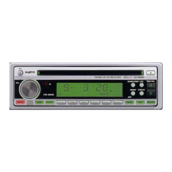
FXD-MP690R
.
FILE NO
FXD-MP690R
114782875
FXD-MP690
114782879
REFERENCE No. SM-0600002
FXD-MP690
Advertisement
Table of Contents

Related Manuals for Sanyo FXD-MP690R


Summary of Contents for Sanyo FXD-MP690R
-
Page 1: Table Of Contents
FILE NO Service Manual FXD-MP690R Full Panel Detachable 114782875 High Power FXD-MP690 FM/AM Stereo 114782879 Receiver Compact Disc Player FXD-MP690R FXD-MP690 Contents SERVICE NOTE AND PRECATIONS.................................... 2 OPERATION CHECK ........................................5 ALIGNMENT LOCATIONS......................................6 ELECTRICAL ADJUSTMENTS...................................... 7 BLOCK DIAGRAM ........................................22 IC/TRANSISTOR LEAD IDENTIFICATION.................................. - Page 2 SPECIFICATIONS FM TUNER Frequency Range ..................FM 87.5 - 108.0 MHz (50 KHz Step) Sensitivity.......................... FM 3 µV (S/N=30 dB) Stereo Separating (FM) ......................30 dB (at 1kHz) Signal to noise ratio (FM)......................Better than 50 dB AM TUNER Frequency Range ..................MW 522 - 1620 kHz (9 KHz Step) Sensitivity........................MW 32 dBµ...
- Page 3 SERVICE NOTES AND PRECAUTIONS: Service notes: Installation procedure: 1. Make sure that the power lead is connected properly to 1. To prevent a short circuit, remove the key from the ignition Power source, otherwise damage to radio may result. If a and disconnect the battery.
-
Page 4: Service Note And Precations
SERVICE NOTES AND PRECAUTIONS 3. Each and every pickup is already individually adjusted to LASER BEAM SAFETY PRECAUTIONS a high degree of precision, and for that reason the adjust- NOTES FOR TRANSPORT AND STORAGE ment point and installation screws should be absolutely 1. - Page 5 SERVICE NOTE AND PRECATUTIONS Static Electricity The CD pickup might suffer destruction by static electricity during spare-parts maintenance or replacement, although it is stable when connected to the circuit in the CD unit. The destruction might caused because the laser diode terminal will be electrically open.
-
Page 6: Operation Check
OPERATION CHECK GENERAL SPECIFICATIONS OF SIGNAL Standard frequency 98.1 MHz (87.5, 108 MHz) 1000 kHz (522, 1620 kHz) 200 kHz (144, 288 kHz) Signal output 1 mV 5 mV 5 mV Modulation 400 Hz 30% MOD. FM Stereo 1 kHz 75 kHz DEV. -
Page 7: Alignment Locations
ALIGNMENT LOCATIONS FM TUNER... - Page 8 ALIGNMENT PROCEDURES FM ADJUSTMENT Equipment Required AM IF/RF signal generator Solid-state voltmeter (SSVM) Regulated DC power supply 2-CH voltmeter Distortion meter FM Alignment Using FM Signal Generator Note: Press the radio power switch to on the radio. Signal generator output must be kept as low as possible to avoid overload and clipping.
- Page 9 RADIO OPERATION FOR FXD-MP690R SWITCHING TO RADIO MODE…………………….…1 Press SOURCE button 1 to select radio mode, the radio mode appears in the display together with the memory band and frequency. SELECTING THE FREQUENCY BAND……………..2 At radio mode, press BAND/LOUD button 2 shortly to select the desired band.
- Page 10 RADIO OPERATION FOR FXD-MP690 SWITCHING TO RADIO MODE…………………….…1 Press SOURCE button 1 to select radio mode, the radio mode appears in the display together with the memory band and frequency. SELECTING THE FREQUENCY BAND……………..2 At radio mode, press BAND/LOUD button 2 shortly to select the desired band. The reception band will change in the following order: RADIO TUNING…………………………………………3 Press the TUN/SEK/TRK...
- Page 11 STORING PRESET STATIONS .........5 The preset buttons 5 can be used to store 6 stations in each band (FM 1, FM 2, FM 3 and MW, LW) for convenient access to your favorite stations. • Programming stations ..1. Select the desired band, then tune in the station you want to store in memory. 2.
- Page 12 RDS (RADIO DATA SYSTEM) OPERATION FOR FXD-MP690R SETTING RDS MODE………………………………1,2,3 Turning RDS on Turn the power on, then press AF/REG button 1 and release immediately to switch on or off RDS mode. Whenever RDS is switch on, symbol “AF” appears on the display.
- Page 13 According to above 2 allotted group, the preset number is used for PTY selection as follows: Preset number PTY Music group PTY SPEECH group POP M, ROCK M NEWS, AFFAIRS, INFO EASY M, LIGHT M SPORT, EDUCATE, DRAMA CLASSICS, OTHER M CULTURE, SCIENCE, VARIED JAZZ, COUNTRY WEATHER, FINANCE, CHILDREN...
- Page 14 CD OPERATION FOR FXD-MP690R & FXD-MP690 FXD-MP690R FXD-MP690 LOADING AND EJECTING THE CD…………………1,8 Insert a disc into the CD slot 1 and the CD player will start. The system remains in CD mode and “ ” appears in the display.
- Page 15 Notes • During playback of a CD, the CD running indicator spins. REPEAT • The unit will turn-on automatically when a CD is inserted if the ignition switch is “ON”. MODE ...........……………..6 Press the RPT button 6 to play the current track repeatedly. To cancel this mode, press the RPT button 6 again.
- Page 16 MP3 OPERATION FOR FXD-MP690R & FXD-MP690 4 15 11 12 13 14 4 15 11 12 13 14 FXD-MP690 FXD-MP690R LOADING AND EJECTING THE MP3…………………1,8 Insert a disc into the disc slot 1 and the player will start. The system remains in MP3 mode and “...
- Page 17 Press BAND/LOUD/ENTER button 5 to start the title search. In case the selected title is a directory name, display will show (‘ ‘), then Use rotary encoder VOL A-Z/0-9 dial 4 to list all songs under this directory and select the title.
- Page 18 MIXED-CD OPERATION FOR FXD-MP690R & FXD-MP690 FXD-MP690 FXD-MP690R This unit can play the mixed-CD disc (the disc contains both CD audio tracks and MP3 files). When you insert a mixed-CD disc into the CD slot, the “ ” appears in the display and it starts to play the CD audio tracks.
- Page 19 AUX MODE OPERATION FOR FXD-MP690R & FXD-MP690 FXD-MP690R FXD-MP690 SWITCHING TO AUX MODE........1 The unit has a pair of auxiliary input terminals (see WIRING figure on page 25). This allows you to listen to an auxiliary audio source (MP3, portable cassette player, etc).
- Page 20 REMOTE CONTROL FOR FXD-MP690R & FXD-MP690 AUD/ 1.POWER 10.PAU 2. AUD/SEL/SET 11.SCN 3. VOL (A~Z, 0~9) 12.RPT 4. VOL (A~Z, 0~9) 13.SHF 5. SOURCE 14.DISP 6. TUN/SEK/TRK 15. DIR 7. TUN/SEK/TRK 16.DIR 8. AS/PS/MP3...
- Page 21 10 seconds, the player will reload the disc to prevent damage. • Servicing Should a problem develop, do not open the unit or try to repair it yourself. If servicing is required, bring the unit to a Sanyo Authorized Service Center.
-
Page 22: Electrical Adjustments
ELECTRICAL ADJUSTMENTS DUMMY BOX SCHEMATIC ● AM DUMMY ANTENNA ● FM DUMMY ANTENNA... -
Page 23: Block Diagram
BLOCK DIAGRAM FOR FXD-MP690R... - Page 24 BLOCK DIAGRAM FOR FXD-MP690...
-
Page 25: Ic/Transistor Lead Identification
IC/TRANSISTOR LEAD IDENTIFICATION FOR FXD-MP690R &FXD-MP690... -
Page 26: Cd Mechanism Exploded View
CD MECHANISM EXPLODED VIEW (MECHANSIM #94-01683-10) - Page 27 SCHEMATIC BOARD DIAGRAM – MAIN FOR FXD-MP690R & FXD-MP690...
- Page 28 SCHEMATIC BOARD DIAGRAM – KEY FOR FXD-MP690R & FXD-MP690 SCHEMATIC BOARD DIAGRAM – ISO FOR FXD-MP690R & FXD-MP690...
- Page 29 SCHEMATIC BOARD DIAGRAM – CD SERVO FOR FXD-MP690R & FXD-MP690...
- Page 30 SCHEMATIC BOARD DIAGRAM – REMOTE FOR FXD-MP690R & FXD-MP690...
- Page 31 NOTE...
- Page 32 FXD-MP690 FXD-MP690R NO. 1702YI31894 Printed In China Issue Date 20-04...
-
Page 33: Cabinet & Chassis Exploded View
CABINET & CHASSIS EXPLODED VIEW... -
Page 34: Part List - Cd Mechanism
PART LIST – CD MECHANISM Ref. No. Parts No. Description RPST-23G SENSOR RPFR 1 SENSOR PCB RPCA/H 0” TT 2*3 SCREW RPSECC T1.0 COVER-UPPER RPPOM (F20-03) 1 LEVER DISC RPPOM (F20-03) 2 GUIDE UP RPPOM (F20-03) 3 BUSHING ROLLER RPSLICON ROLLER DISC RPSUS 303 SHAFT ROLLER... - Page 35 PART LIST – CD MECHANISM Ref. No. Parts No. Description RPPOM (F20-03) 18 CLAMP DISC RPSECC T1.0 3 HOLD CLAMPER RPSUS304WPB 5 S/P CLAMPER RPABS G/F 20% TURN TABLE RPPOM (F20-03) 19 BASE PU RPSUM24L-NI 5 PIN SIDE (A) RPCA/H 0” M/S 1.7*2.5 SCREW RPSUM24L-NI 6 PIN SIDE (B)
-
Page 36: Part List Key
PART LIST CABINET & CHASSIS Ref. No. Part No. Description Panel RP51-V3626-80B Trim Ring (S. OPC1202) RP51-V3620-00 Base (For CD) RP94-01683-10 CD MECHA. CDM-1683 EUR (143A W/O PCB) RP61-V3601-00 Main Bracket (CD) RP61-V3604-00 Bottom Cover RP35-V3601-00 Main Fiber RP11-17025-025 Main Board RP61-V3603-00 Mounting Box RP81-68608-01... - Page 37 ACCESSORY EXPLODED VIEW Locking Screw Mounting Strap Unlock Levers Carrying Case ACCESSORY – PART LIST Ref. No. Part No. Description RP35-40005-00 HEXAGON NUT M5 RP35-50001-00 SPRING WASHER M5 RP39-00128-00 METAL BAR (197MM) RP40-05006-07 SCREW Ø5X6 RH/MS RP40-15025-11 SCREW Ø5X25 TA/ST RP39-V3610-00 KEY (1.0) RP51-A8026-00...
- Page 38 PARTS LIST MAIN CIRCUIT BOARD FOR FXD-MP690R, FXD-MP690 ●: FXD-MP690R ▲: FXD-MP690 Ref. No. Part No. Description Q810 RP01-00435-00S TR. BD435 NPN TO-126 SAMSUNG Q208,603,802,TEL-Q1 RP01-00812-00 TR. 2SA812 Q812 RP01-01240-00 TRANSISTOR B1240 Q209~11,801/3~6/8,811 RP01-03875-07 TRANSISTOR 2SC3875G IC804 RP01-07805-00 IC-REGULATOR 78L05...
- Page 39 MAIN CIRCUIT BOARD FOR FXD-MP690R, FXD-MP690 Ref. No. Part No. Description C212,641,809,812 RP06-16106-02E E. CAP 10µF/16V (4X5MM RC3) C701 RP06-16107-04 E. CAP 100µF 16V (Ø6X5MM) C618 RP06-16226-02 E. CAP 22µF 16V (Ø5X5MM) C810 RP06-16338-00S E. CAP 3300µF 16V 105°C C841 RP06-16475-02 E.
- Page 40 MAIN CIRCUIT BOARD FOR FXD-MP690R, FXD-MP690 Ref. No. Part No. Description R809~12 RP07-63561-00 CHIP RES. 560Ω ±5% 0603 SMT R836/8 RP07-63683-00 CHIP RES. 68kΩ ±5% 0603 SMT R705/8,711/4 RP07-63822-00 CHIP RES. 8.2kΩ ±5% 0603 SMT R603 RP07-63823-00 CHIP RES. 82kΩ ±5% 0603 SMT...
- Page 41 FM TUNER SECTION FOR FXD-MP690R, FXD-MP690 ● ▲ : FXD-MP690R : FXD-MP690 Ref. No. Part No. Description Q204~7 RP01-03875-07 TRANSISTOR 2SC3875G D201 RP02-04148-00A DIODE IN-4148 AT. (TAPPING) ● IC202 RP03-06579-00 IC SAA-6579T ● XT201 RP04-00433-00M C. 4.332MHZ HC-49U 30PPM 22PF ●...
- Page 42 AM TUNER SECTION FOR FXD-MP690R, FXD-MP690 Ref. No. Part No. Description Q203 RP01-00812-00 TR. 2SA812 Q201/2 RP01-03875-07 TRANSISTOR 2SC3875G D202,641/4 RP02-04148-00A DIODE IN-4148 AT. (TAPPING) C208 RP05-16225-00 TAN CAP 2.2µF 16V C206 RP05-63103-01 CHIP 0.01µF ±10% X7R 0603 SMT C201~3 RP05-63223-01 CHIP 0.022µF ±10% X7R 0603 SMT...
- Page 43 KEY CIRCUIT BOARD FOR FXD-MP690R, FXD-MP690 Ref. No. Part No. Description ZD101 RP02-00062-07 E.S.D. DIODE NNCD6.2G (5PIN) LED1 RP02-01112-02 SMD LED FR1112H (RED) STANLEY LED2~25 RP02-01112-03F FA1112H (ORANGE) SMD LED “STANLEY” RP02-A1702-23 CD1702 LCD B.L. 97X17 AMBER IC101 RP03-75823-00 IC LC75823ED...
- Page 44 CD SERVO CIRCUIT BOARD FOR FXD-MP6P0R, FXD-MP690 Ref. No. Part No. Description Q2~6 RP01-00103-00 TR. KEC103S RP01-00106-00 KRA106S (SOT-23) Q305 RP01-00435-00S TR. BD435 NPN TO-126 SAMSUNG Q1,302/4 RP01-00812-00 TR. 2SA812 RP01-01225-13 TRANSISTOR 2SD1225M Q301/3 RP01-03875-07 TRANSISTOR 2SC3875G D1,2 RP02-00144-00 IR LED MIE 144A1MC D5,6 RP02-04148-00 DIODE IN-4148...
- Page 45 CD SERVO CIRCUIT BOARD FOR FXD-MP690R, FXD-MP690 Ref. No. Part No. Description R305 RP07-05103-16A RES. 10kΩ 1/16W (TAPPING) R313 RP07-05472-16A RES. 4.7kΩ 1/16W (TAPPING) R102,120,204~7,213/6,244,251/2,303 RP07-63000-00 CHIP RES 0Ω 0603 SMT R236,255,264,304 RP07-63015-00 CHIP RES 1.5Ω 0603 SMT R105 RP07-63100-00 CHIP RES 10Ω...
- Page 46 REMOTE CIRCUIT BOARD FOR FXD-MP690R, FXD-MP690 Ref. No. Part No. Description Q500 RP01-01781-18 TR. 2SD1781K-R “ROHM” RP02-00334-00 INFRARED LED Ø3MM MIE-334A4 D500/1 RP02-04148-00 DIODE IN-4148 IC500 RP03-00101-00 IC S0101 (SGNEC) C504 RP05-03105-10M CHIP CAP KC20E1C105M-TS C501/2 RP05-03121-06 CHIP CAP. 120PF (NPO)
-
Page 47: Schematic Diagram
SCHEMATIC DIAGRAM – MAIN BOARD FOR FXD-MP690R & FXD-MP690... - Page 48 SCHEMATIC DIAGRAM – KEY BOARD FOR FXD-MP690R & FXD-MP690...
- Page 49 SCHEMATIC DIAGRAM – CD SERVO BOARD FOR FXD-690R & FXD-MP690...
- Page 50 SCHEMATIC DIAGRAM – REMOTE BOARD FOR FXD-690R & FXD-MP690...
Need help?
Do you have a question about the FXD-MP690R and is the answer not in the manual?
Questions and answers