Advertisement
Quick Links
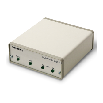
Trunk Interface II
Product Description
The Trunk Interface II (Figure 1) conversely converts
RS-232 signals to PMD or LAN trunk signals.
NOTE: If you are connecting an MBC-based Open
Processor Driver, see Installation
Instructions (565-950).
Product Numbers
538-670 Trunk Interface II, 115 Vac power pack
538-675 Trunk Interface II, 230 Vac power pack
Required Tools
• Medium flat-blade screwdriver
• Medium Phillips screwdriver
• Wire strippers
Expected Installation Time
10 minutes (P2 Network)
15 minutes (P1 Network)
Figure 1. Trunk Interface II.
Installation Instructions
Prerequisites
The Trunk Interface II can be placed either on a
desk or inside a wall enclosure. For either
placement, the Trunk Interface II must be located
within four feet (1.2 m) of a power receptacle to
allow the power pack DC cable and earth ground
reference wire to reach the Trunk Interface II.
For desk placement
• Computer in place and RS-232 cable
assembled and connected to the computer's
RS-232 port.
• All PMD trunk wiring installed and tested for
opens and shorts.
• Source of transient protected AC power
available.
For placement inside an enclosure
• Enclosure mounted.
• Transient protected outlet installed, (529-804).
(All standard APOGEE field panels contain
transient protected outlets.)
• All BLN trunk wiring installed and tested for
opens and shorts.
NOTE: To comply with installations requiring
Class 1 conduit connections, place the
Trunk Interface II in the field panel
enclosure.
Installation
P1 Trunk Applications
1.
Unscrew the two Phillips screws on the front of
the Trunk Interface II enclosure and remove the
enclosure cover.
2.
To change to an RCU or RPU P1 trunk
application, install jumpers one and two so that
they short their respective pins. The jumpers
are factory installed in a non-shorting position.
See Figure 2 for the location of the jumpers.
3.
Replace the Trunk Interface II cover and attach
with the 2 Phillips screws removed in Step 2.
Document No. 538-663
Rev. 5, April, 2002
Page 1 of 2
Advertisement

Related Manuals for Siemens Trunk Interface II Series


Summary of Contents for Siemens Trunk Interface II Series
-
Page 1: Product Description
Installation Instructions Document No. 538-663 Rev. 5, April, 2002 Trunk Interface II Prerequisites Product Description The Trunk Interface II can be placed either on a The Trunk Interface II (Figure 1) conversely converts desk or inside a wall enclosure. For either RS-232 signals to PMD or LAN trunk signals. - Page 2 Information in this publication is based on current specifications. The company reserves the right to make changes in specifications and models as design improvements are introduced. Other product or company names mentioned herein may be trademarks of their respective owners. © 2002 Siemens Building Technologies, Inc. Siemens Building Technologies, Inc.
Need help?
Do you have a question about the Trunk Interface II Series and is the answer not in the manual?
Questions and answers