National Instruments PXI-1031DC User Manual
Hide thumbs
Also See for PXI-1031DC:
- Installation manual (2 pages) ,
- User manual (64 pages) ,
- User manual (62 pages)

Related Manuals for National Instruments PXI-1031DC


Summary of Contents for National Instruments PXI-1031DC
- Page 1 (217) 352-9330 | Click HERE Find the National Instruments PXI-1031 at our website:...
- Page 2 NI PXI-1031/PXI-1031DC User Manual NI PXI-1031/PXI-1031DC User Manual December 2010 371226G-01 Artisan Technology Group - Quality Instrumentation ... Guaranteed | (888) 88-SOURCE | www.artisantg.com...
- Page 3 Thailand 662 278 6777, Turkey 90 212 279 3031, United Kingdom 44 (0) 1635 523545 For further support information, refer to the Technical Support and Professional Services appendix. To comment on National Instruments documentation, refer to the National Instruments Web site at and enter ni.com/info the Info Code feedback ©...
- Page 4 Instruments Corporation. National Instruments respects the intellectual property of others, and we ask our users to do the same. NI software is protected by copyright and other intellectual property laws. Where NI software may be used to reproduce software or other materials belonging to others, you may use NI software only to reproduce materials that you may reproduce in accordance with the terms of any applicable license or other legal restriction.
-
Page 5: Table Of Contents
Installing Filler Panels..................2-3 Rack Mounting ......................2-4 Connecting Safety Ground.....................2-4 Connecting to Power Source..................2-4 Connecting to an AC Power Source..............2-5 Connecting to a DC Power Source (PXI-1031DC Only)........2-5 DC Connector ...................2-5 Installing a PXI Controller.....................2-6 © National Instruments Corporation NI PXI-1031/PXI-1031DC User Manual... - Page 6 Basic PXI System Configuration ..............2-10 Trigger Configuration in MAX............... 2-11 Using System Configuration and Initialization Files ............ 2-11 Chapter 3 Maintenance DC Fuse Replacement (PXI-1031DC Only) ..............3-1 Service Interval......................3-1 Preparation........................3-1 Cleaning......................... 3-2 Interior Cleaning ..................... 3-2 Exterior Cleaning ....................
-
Page 7: About This Manual
About This Manual The NI PXI-1031/PXI-1031DC User Manual contains information about installing, configuring, using, and maintaining the NI PXI-1031 and PXI-1031DC chassis. Conventions The following conventions are used in this manual: » The » symbol leads you through nested menu items and dialog box options to a final action. -
Page 8: Related Documentation
About This Manual Related Documentation The following documents contain information that you may find helpful as you read this manual: • NI PXI-1031DC DC Cable Kit Installation Guide • CompactPCI Specification PICMG 2.0 R 3.0 • PXI Hardware Specification •... -
Page 9: Getting Started
Getting Started This chapter describes the key features of the NI PXI-1031 and PXI-1031DC chassis, and lists the kit contents and optional equipment you can order from National Instruments. Unpacking Carefully inspect the shipping container and the chassis for damage. Check for visible damage to the metal work. -
Page 10: Key Features
If you are missing any of the items listed in Table 1-1, or if you have the incorrect AC power cable, contact National Instruments. You have the option of powering the PXI-1031DC chassis with a DC power cable through the DC input connector on the rear panel of the chassis. Refer to Figure 1-3 for the location of the DC connector. -
Page 11: Chassis Description
Figure 1-2 shows the rear view of the PXI-1031. Figure 1-3 shows the rear panel of the PXI-1031DC. Figure 1-4 shows the bottom of the chassis (both types of chassis will be identical on the bottom). - Page 12 3 DC Input 7 AUTO/HIGH Fan Speed Selector Switch 4 AC Input 8 Rubber Foot Figure 1-3. Rear View of the PXI-1031DC Chassis NI PXI-1031/PXI-1031DC User Manual ni.com Artisan Technology Group - Quality Instrumentation ... Guaranteed | (888) 88-SOURCE | www.artisantg.com...
-
Page 13: Optional Equipment
2 Fan Cover 4 Rubber Foot Figure 1-4. Bottom View of PXI-1031/PXI-1031DC Chassis Optional Equipment Contact National Instruments to order the following options for the PXI-1031/PXI-1031DC chassis. EMC Filler Panels Optional EMC filler panel kits are available from National Instruments. -
Page 14: Dc Power Cable (Pxi-1031Dc Only)
Chapter 1 Getting Started DC Power Cable (PXI-1031DC Only) An optional DC power cable is available from National Instruments to provide power through the DC input connector on the rear panel of the chassis. PXI-1031/PXI-1031DC Backplane Overview Interoperability with CompactPCI The PXI-1031/PXI-1031DC backplane is interoperable with 5 V and universal PXI-compatible products and standard CompactPCI products. -
Page 15: Star Trigger Slot
PXI bus bandwidth. Initialization software uses the configuration information specific to adjacent peripheral modules to evaluate local bus compatibility. © National Instruments Corporation NI PXI-1031/PXI-1031DC User Manual Artisan Technology Group - Quality Instrumentation ... Guaranteed | (888) 88-SOURCE | www.artisantg.com... -
Page 16: Trigger Bus
System Reference Clock The PXI-1031/PXI-1031DC supplies the PXI 10 MHz system clock signal (PXI_CLK10) independently to each peripheral slot. An independent buffer (having a source impedance matched to the backplane and a skew of less than 250 ps between slots) drives the clock signal to each peripheral slot. -
Page 17: Installation And Configuration
Under such conditions, this equipment is unsafe and may ignite the gases or gas fumes. © National Instruments Corporation NI PXI-1031/PXI-1031DC User Manual Artisan Technology Group - Quality Instrumentation ... Guaranteed | (888) 88-SOURCE | www.artisantg.com... -
Page 18: Chassis Cooling Considerations
Part Replacement—Only service this equipment with parts that are exact replacements, both electrically and mechanically. Contact National Instruments for replacement part information. Installation of parts with those that are not direct replacements may cause harm to personnel operating the chassis. Furthermore, damage or fire may occur if replacement parts are unsuitable. -
Page 19: Setting Fan Speed
Installation and Configuration 1 Air Outlets 2 Air Intake Figure 2-1. PXI-1031/PXI-1031DC Module Cooling Airflow Side View Install the chassis so that you can easily access the bottom panel. Setting Fan Speed The AUTO/HIGH fan-speed selector switch is on the rear panel of the PXI-1031 and PXI-1031DC. -
Page 20: Rack Mounting
You may want to remove the feet from the chassis when rack mounting. To do so, remove the screws holding the feet in place. Connecting Safety Ground The PXI-1031/PXI-1031DC chassis is designed with a three-position inlet that Caution connects the cord set ground line to the chassis ground. To minimize shock hazard, make sure the electrical power outlet you use to power the chassis has an appropriate earth safety ground. -
Page 21: Connecting To An Ac Power Source
The power switch allows you to power on the chassis or place it in standby mode. Press the power switch to the On position (if not already on). Observe that all fans become operational. Connecting to a DC Power Source (PXI-1031DC Only) Table 2-1. DC Power Requirements Electrical Element... -
Page 22: Installing A Pxi Controller
A Ferraz-Shawmut FEB-81-81 fuse holder, with Ferraz-Shawmut FSB1 insulating boots, and an ATM30 fuse is recommended. Refer to the NI PXI-1031DC DC Cable Kit Installation Guide for information on fuse installation. Note You can purchase an optional DC cable from National Instruments that incorporates an in-line fuse and the mating connector for the P1 port. - Page 23 Power on the chassis. Verify that the controller boots. If the controller does not boot, refer to your controller user manual. © National Instruments Corporation NI PXI-1031/PXI-1031DC User Manual Artisan Technology Group - Quality Instrumentation ... Guaranteed | (888) 88-SOURCE | www.artisantg.com...
-
Page 24: Installing Pxi Modules
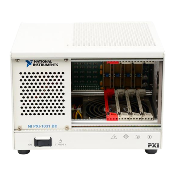
1 PXI-1031/PXI-1031DC Chassis 3 NI PXI Controller 2 Injector/Ejector Rail Figure 2-4. NI PXI Controller Installed in a PXI-1031/PXI-1031DC Chassis Installing PXI Modules Complete the following steps to install a module. Make sure the power switch is in the Off (Standby) position. -
Page 25: Pxi System Configuration With Max
NI Driver CD-ROM, the MAX icon will be present on the desktop. The configuration steps for single or multiple chassis systems are the same. © National Instruments Corporation NI PXI-1031/PXI-1031DC User Manual Artisan Technology Group - Quality Instrumentation ... Guaranteed | (888) 88-SOURCE | www.artisantg.com... -
Page 26: Basic Pxi System Configuration
NI-VISA. After your controller and all of your chassis have been identified, the required file will be pxisys.ini complete. NI PXI-1031/PXI-1031DC User Manual 2-10 ni.com Artisan Technology Group - Quality Instrumentation ... Guaranteed | (888) 88-SOURCE | www.artisantg.com... -
Page 27: Trigger Configuration In Max
“pre-allocates” a trigger line to prevent its configuration by a user program. Dynamic reservation/routing/deallocation is performed on the fly within a user program based upon National Instruments APIs such as NI-DAQmx. Static reservation of trigger lines can be implemented by the user in MAX through the Triggers tab. - Page 28 Chapter 2 Installation and Configuration The capability documentation for the PXI-1031/PXI-1031DC chassis is contained in the file on the software media that comes chassis.ini with the chassis. The information in this file is combined with information about the system controller to create a single system initialization file called (PXI System Initialization).
-
Page 29: Maintenance
Disconnect the power cables prior to servicing the chassis. DC Fuse Replacement (PXI-1031DC Only) The PXI-1031DC is protected against over-current by a 30 A fuse on the rear of the chassis, as shown in Figure 1-3, Rear View of the PXI-1031DC Chassis. -
Page 30: Cleaning
Caution Always disconnect the AC power cable (and the DC power cable, if you are working with a PXI-1031DC chassis) before cleaning or servicing the chassis. Cleaning procedures consist of exterior and interior cleaning of the chassis. Refer to your module user documentation for information on cleaning individual CompactPCI or PXI modules. - Page 31 Specifications If the PXI-1031/PXI-1031DC chassis is used in a manner inconsistent with the Caution instructions or specifications listed by National Instruments, the protective features of the chassis may be impaired. Note Specifications are subject to change without notice. This appendix contains specifications for the PXI-1031 and PXI-1031DC chassis.
- Page 32 Module cooling System ..........Forced air circulation (positive pressurization) through a 101.1 CFM fan with HIGH/AUTO speed selector Intake ..........Bottom of chassis NI PXI-1031/PXI-1031DC User Manual ni.com Artisan Technology Group - Quality Instrumentation ... Guaranteed | (888) 88-SOURCE | www.artisantg.com...
- Page 33 IEC-60068-2-2. Meets MIL-PRF-28800F Class 3 limits.) Relative humidity range ......10 to 95%, noncondensing (Tested in accordance with IEC-60068-2-56.) © National Instruments Corporation NI PXI-1031/PXI-1031DC User Manual Artisan Technology Group - Quality Instrumentation ... Guaranteed | (888) 88-SOURCE | www.artisantg.com...
- Page 34 High fan ...........51.7 dBA Sound Power Tested in accordance with ISO 7779. PXI-1031 Auto fan (at 25 °C ambient) ....43.4 dBA High fan ...........59.5 dBA NI PXI-1031/PXI-1031DC User Manual ni.com Artisan Technology Group - Quality Instrumentation ... Guaranteed | (888) 88-SOURCE | www.artisantg.com...
- Page 35 Input voltage range......... 18–30 VDC Input current rating......... 30–10 A Efficiency ..........65% typical The operating range is guaranteed by design. © National Instruments Corporation NI PXI-1031/PXI-1031DC User Manual Artisan Technology Group - Quality Instrumentation ... Guaranteed | (888) 88-SOURCE | www.artisantg.com...
- Page 36 Chassis Cooling Per slot cooling capacity......25 W Slot airflow direction ......P1 to P2, bottom of module to top of module NI PXI-1031/PXI-1031DC User Manual ni.com Artisan Technology Group - Quality Instrumentation ... Guaranteed | (888) 88-SOURCE | www.artisantg.com...
- Page 37 (Tested in accordance with IEC-60068-2-1 and IEC-60068-2-2.) Relative humidity range ......5 to 95%, noncondensing (Tested in accordance with IEC-60068-2-56.) © National Instruments Corporation NI PXI-1031/PXI-1031DC User Manual Artisan Technology Group - Quality Instrumentation ... Guaranteed | (888) 88-SOURCE | www.artisantg.com...
- Page 38 High fan ...........49.4 dBA Sound Power Tested in accordance with ISO 7779. PXI-1031DC Auto fan (at 25 °C ambient) ....54.3 dBA High fan ...........58.2 dBA NI PXI-1031/PXI-1031DC User Manual ni.com Artisan Technology Group - Quality Instrumentation ... Guaranteed | (888) 88-SOURCE | www.artisantg.com...
- Page 39 This product meets the essential requirements of applicable European Directives as follows: • 2006/95/EC; Low-Voltage Directive (safety) • 2004/108/EC; Electromagnetic Compatibility Directive (EMC) © National Instruments Corporation NI PXI-1031/PXI-1031DC User Manual Artisan Technology Group - Quality Instrumentation ... Guaranteed | (888) 88-SOURCE | www.artisantg.com...
- Page 40 Compliant with IEEE 1101.10 mechanical packaging. PXI Hardware Specification, Revision 2.2 compliant. Accepts both PXI and CompactPCI 3U modules. NI PXI-1031/PXI-1031DC User Manual A-10 ni.com Artisan Technology Group - Quality Instrumentation ... Guaranteed | (888) 88-SOURCE | www.artisantg.com...
- Page 41 V(I/O) is connected to the +5 V DC power plane, so the same specifications apply to V(I/O) and +5 V. © National Instruments Corporation A-11 NI PXI-1031/PXI-1031DC User Manual Artisan Technology Group - Quality Instrumentation ... Guaranteed | (888) 88-SOURCE | www.artisantg.com...
- Page 42 Module Front Panel 0.96 in. (24.38 mm) 8.43 in. (214.2 mm) Figure A-1. PXI-1031/PXI-1031DC Dimensions (Front and Side) in Inches (mm) NI PXI-1031/PXI-1031DC User Manual A-12 ni.com Artisan Technology Group - Quality Instrumentation ... Guaranteed | (888) 88-SOURCE | www.artisantg.com...
- Page 43 (222 mm) 0.89 in. (22.6 mm) 6.49 in. (164.85 mm) Figure A-2. PXI-1031/PXI-1031DC Dimensions (Bottom) in Inches (mm) © National Instruments Corporation A-13 NI PXI-1031/PXI-1031DC User Manual Artisan Technology Group - Quality Instrumentation ... Guaranteed | (888) 88-SOURCE | www.artisantg.com...
- Page 44 Appendix A Specifications Figure A-3 shows the PXI-1031/PXI-1031DC rack mount kit components. I - 1 1 PXI-1031/PXI-1031DC Chassis 2 Rack Mount Kit Figure A-3. PXI-1031/PXI-1031DC Rack Mount Kit Components NI PXI-1031/PXI-1031DC User Manual A-14 ni.com Artisan Technology Group - Quality Instrumentation ... Guaranteed | (888) 88-SOURCE | www.artisantg.com...
- Page 45 Table B-6 shows the P2 (J2) connector pinout for the peripheral slots. Note PXI signals are shown in bold. © National Instruments Corporation NI PXI-1031/PXI-1031DC User Manual Artisan Technology Group - Quality Instrumentation ... Guaranteed | (888) 88-SOURCE | www.artisantg.com...
- Page 46 AD[27] REQ# 3.3 V AD[31] BRSVP1A5 BRSVP1B5 RST# GNT# BRSVP1A4 V(I/O) INTP INTS INTA# INTB# INTC# INTD# –12 V TRST# +12 V NI PXI-1031/PXI-1031DC User Manual ni.com Artisan Technology Group - Quality Instrumentation ... Guaranteed | (888) 88-SOURCE | www.artisantg.com...
- Page 47 BP(I/O) BP(I/O) V(I/O) PXI_BRSVB4 BP(I/O) BP(I/O) CLK4 GNT3# REQ4# GNT4# CLK2 CLK3 SYSEN# GNT2# REQ3# CLK1 REQ1# GNT1# REQ2# © National Instruments Corporation NI PXI-1031/PXI-1031DC User Manual Artisan Technology Group - Quality Instrumentation ... Guaranteed | (888) 88-SOURCE | www.artisantg.com...
- Page 48 AD[27] REQ# 3.3 V AD[31] BRSVP1A5 BRSVP1B5 RST# GNT# BRSVP1A4 V(I/O) INTP INTS INTA# INTB# INTC# INTD# –12 V TRST# +12 V NI PXI-1031/PXI-1031DC User Manual ni.com Artisan Technology Group - Quality Instrumentation ... Guaranteed | (888) 88-SOURCE | www.artisantg.com...
- Page 49 V(I/O) V(I/O) V(I/O) 64EN# V(I/O) V(I/O) PXI_BRSVB4 PXI_LBR7 PXI_LBR8 PXI_LBR9 PXI_LBR10 PXI_LBR11 PXI_LBR12 PXI_STAR7 PXI_STAR8 PXI_STAR9 PXI_STAR10 PXI_STAR11 PXI_STAR12 © National Instruments Corporation NI PXI-1031/PXI-1031DC User Manual Artisan Technology Group - Quality Instrumentation ... Guaranteed | (888) 88-SOURCE | www.artisantg.com...
- Page 50 AD[27] REQ# 3.3 V AD[31] BRSVP1A5 BRSVP1B5 RST# GNT# BRSVP1A4 V(I/O) INTP INTS INTA# INTB# INTC# INTD# –12 V TRST# +12 V NI PXI-1031/PXI-1031DC User Manual ni.com Artisan Technology Group - Quality Instrumentation ... Guaranteed | (888) 88-SOURCE | www.artisantg.com...
- Page 51 V(I/O) V(I/O) V(I/O) 64EN# V(I/O) V(I/O) PXI_BRSVB4 PXI_LBR7 PXI_LBR8 PXI_LBR9 PXI_LBR10 PXI_LBR11 PXI_LBR12 PXI_LBL7 PXI_LBL8 PXI_LBL9 PXI_LBL10 PXI_LBL11 PXI_LBL12 © National Instruments Corporation NI PXI-1031/PXI-1031DC User Manual Artisan Technology Group - Quality Instrumentation ... Guaranteed | (888) 88-SOURCE | www.artisantg.com...
- Page 52 Technical Support and Professional Services Visit the following sections of the award-winning National Instruments Web site at for technical support and professional services: ni.com • Support—Technical support at includes the ni.com/support following resources: – Self-Help Technical Resources—For answers and solutions,...
- Page 53 Worldwide Offices section of to access the branch ni.com/niglobal office Web sites, which provide up-to-date contact information, support phone numbers, email addresses, and current events. NI PXI-1031/PXI-1031DC User Manual ni.com Artisan Technology Group - Quality Instrumentation ... Guaranteed | (888) 88-SOURCE | www.artisantg.com...
- Page 54 Percent Ohms Amperes Alternating current ANSI American National Standards Institute AUTO Automatic fan speed control American Wire Gauge © National Instruments Corporation NI PXI-1031/PXI-1031DC User Manual Artisan Technology Group - Quality Instrumentation ... Guaranteed | (888) 88-SOURCE | www.artisantg.com...
- Page 55 Direct current Declaration of Conformity efficiency Ratio of output power to input power, expressed as a percentage Electronic Industries Association NI PXI-1031/PXI-1031DC User Manual ni.com Artisan Technology Group - Quality Instrumentation ... Guaranteed | (888) 88-SOURCE | www.artisantg.com...
- Page 56 International Electrotechnical Commission; an organization that sets international electrical and electronics standards IEEE Institute of Electrical and Electronics Engineers Mainframe peak current © National Instruments Corporation NI PXI-1031/PXI-1031DC User Manual Artisan Technology Group - Quality Instrumentation ... Guaranteed | (888) 88-SOURCE | www.artisantg.com...
- Page 57 Megahertz. One million Hertz; one Hertz equals one cycle per second. –3 Millisecond, one thousandth of a second (10 NEMA National Electrical Manufacturers Association National Instruments NI PXI-1031/PXI-1031DC User Manual ni.com Artisan Technology Group - Quality Instrumentation ... Guaranteed | (888) 88-SOURCE | www.artisantg.com...
- Page 58 Glossary NI-DAQmx National Instruments driver that controls the operation of National Instruments data acquisition (DAQ) devices NI-VISA National Instruments implementation of the VISA (Virtual Instrument System Architecture) I/O standard. NI-VISA provides support for the VISA API, and also provides VISAIC, a utility for instrument configuration and I/O function execution.
- Page 59 The PXI backplane specification defines implementation guidelines for PXI_CLK10. Transistor-transistor logic Underwriter’s Laboratories Volts Volts alternating current, or V Peak-to-peak voltage Watts NI PXI-1031/PXI-1031DC User Manual ni.com Artisan Technology Group - Quality Instrumentation ... Guaranteed | (888) 88-SOURCE | www.artisantg.com...
- Page 60 2-4 conventions used in the manual, vii cooling air cooling of PXI-1031, 2-2 handle/feet kit, 1-5 air cooling of PXI-1031DC, 2-2 help, technical support, C-1 air intake (figure), 2-3 filler panel installation, 2-3 setting fan speed, 2-3 © National Instruments Corporation NI PXI-1031/PXI-1031DC User Manual Artisan Technology Group - Quality Instrumentation ...
- Page 61 3-1 PXI controller installed in a PXI-1031 service interval, 3-1 chassis (figure), 2-8 static discharge damage (caution), 3-1 PXI controller installed in a PXI-1031DC chassis (figure), 2-8 rack mounting, 2-4 setting fan speed, 2-3 National Instruments support and site considerations, 2-2...
- Page 62 2-6 overview, 1-6 installing in a PXI-1031 chassis peripheral slots, 1-7 (figure), 2-8 star trigger (ST) slot, 1-7 installing in a PXI-1031DC chassis system reference clock, 1-8 (figure), 2-8 trigger bus, 1-8 PXI subsystem bottom view of chassis, 1-5...
- Page 63 PXI-1031DC, 1-1 specifications, PXI-1031DC acoustic emissions, A-8 sound power, A-8 sound pressure level (at operator Web resources, C-1 position), A-8 chassis cooling, A-6 NI PXI-1031/PXI-1031DC User Manual ni.com Artisan Technology Group - Quality Instrumentation ... Guaranteed | (888) 88-SOURCE | www.artisantg.com...
Need help?
Do you have a question about the PXI-1031DC and is the answer not in the manual?
Questions and answers