Table of Contents
Advertisement
Quick Links
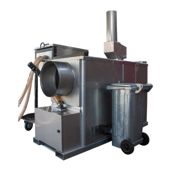
THERMOBILE
IMAC 2000 PELLET
41.731.000
THERMOBILE INDUSTRIES V
Konijnenberg 80
4825 BD Breda Nederland
Postbus 3312
4800 DH Breda Nederland
Bedrijfsnummer: 3502
T +31 (0)76 587 34 50
F +31 (0)76 587 27 89
info@thermobile.com
www.thermobile.com
THERMOBILE INDUSTRIES BV
THERMOBILE UK LTD
12, Buckingham Close
Bermuda Industrial Estate
Nuneaton, Warwickshire
CV10 7JT
Groot-Brittannië
T +44 (0)2476 35 79 60
F +44 (0)2476 35 79 69
info@thermobile.co.uk
www.thermobile.co.uk
THERMOBILE FRANCE sarl
3, rue Denis Papin
45240 LA FERTÉ ST. AUBIN
Frankrijk
T +33 (0)2 38 76 59 25
F +33 (0)2 38 76 58 93
info@thermobile.fr
www.thermobile.fr
1
Advertisement
Table of Contents

Related Manuals for THERMOBILE IMAC 2000 PELLET


Summary of Contents for THERMOBILE IMAC 2000 PELLET
- Page 1 THERMOBILE INDUSTRIES BV THERMOBILE IMAC 2000 PELLET 41.731.000 THERMOBILE INDUSTRIES V THERMOBILE UK LTD THERMOBILE FRANCE sarl Konijnenberg 80 12, Buckingham Close 3, rue Denis Papin 4825 BD Breda Nederland Bermuda Industrial Estate 45240 LA FERTÉ ST. AUBIN Nuneaton, Warwickshire...
- Page 2 THERMOBILE INDUSTRIES BV Fig 1 Fig 2 Fig 3 Fig 4 INSTRUCTIONMANUAL PELLETHEATER...
- Page 3 THERMOBILE INDUSTRIES BV INSTRUCTIONMANUAL PELLETHEATER...
- Page 4 THERMOBILE INDUSTRIES BV 1) CONTAINER 10ft 2) MAULWURF 3) PELLET SUCTION HOSE MAX OPERATING DISTANCE 20M 4) HEATER 5) EXHAUST FAN 8) AIR HOSE 6) ASHCONTAINER 7) PELLETSTORAGE Fig 6 INSTRUCTIONMANUAL PELLETHEATER...
- Page 5 THERMOBILE INDUSTRIES BV Fig 7 Fig 8 In case no external thermostat is used the Installation exhaust fan. cap must be placed in the connector as shown. Fig 10 Fig 11 Mounting the ash auger. Positioning and mounting the ash bin.
- Page 6 THERMOBILE INDUSTRIES BV Power Maulwurf Refill container Pellets Pellets Connecting the 10ft container to the temporary pellet storage Fig 12 Power Pellets from 10ft container Air to Power to 10ft container maulwurf Fig 13 Mounting the Pellet Pellet slide Power pellet auger.
-
Page 7: Table Of Contents
THERMOBILE INDUSTRIES BV Contents Safety instructions Introduction Preparations and main components. Operation Maintenance. Troubleshooting Spareparts Technical information Installation of accessories EC Declaration of conformity APENDIX INSTRUCTIONMANUAL PELLETHEATER... -
Page 8: Safety Instructions
THERMOBILE INDUSTRIES BV Preface This manual contains the instructions for use of the convector heater shown on the cover. The information in this manual is important for the correct and safe operation of the convector heater. Identification of the product (Fig. 1) The identification plate is mounted on the side of the convector heater. -
Page 9: Introduction
THERMOBILE INDUSTRIES BV Some surfaces may be hot! Wait until these parts have cooled down before carrying out any maintenance. Suggestions and tips to facilitate the necessary tasks or actions. Lifting instructions (Fig. 2) Lifting hooks Shafts for lifting using a fork-lift truck Warning Do not use any unsuitable material for lifting the convector heater. -
Page 10: Instructionmanual Pelletheater
THERMOBILE INDUSTRIES BV A room thermostat can be connected to the control cabinet. It can be used to control the temperature in the room to be heated. The external auger transports the pellets from a pellet container to the burner. The controller... - Page 11 THERMOBILE INDUSTRIES BV Control panel(Fig. 4) Indicator light, blue: Ventilator is running Indicator light, white: Panel is live Indicator light, orange: Burner in operation Hour counter Digital thermostat Pushbutton with indicator light, red: Burner reset Indicator light, red: Ventilator overload...
- Page 12 THERMOBILE INDUSTRIES BV PREPARATIONS Caution Make sure to always follow the local standards and guidelines. Removing the packaging Remove the packaging material from the convector heater. Lift the convector heater to transport it to its location of use. Caution Lift the convector heater according to the instructions (fig. 2).
-
Page 13: Operation
THERMOBILE INDUSTRIES BV OPERATION During operation Hot Do not touch the flue and exhaust opening! The flue and exhaust opening will become hot during operation!! Switching off To switch off the heating: Switch the rotary switch to position “0”. The pellet supply will stop and the pellets that are inside the heater will burn out. -
Page 14: Maintenance
THERMOBILE INDUSTRIES BV MAINTENANCE Maintenance table After each winter season, register any maintenance carried out in the table at the back of this manual. Description Period Check and clean burnerchamber and heat exchanger 2 times a week 2000 kg pellets... -
Page 15: Troubleshooting
THERMOBILE INDUSTRIES BV TROUBLESHOOTING Make sure the electric power supply is switched off and the fuel tank is full, before you start troubleshooting. Warning Switch off the power supply before carrying out any repairs! Troubleshooting table Fault Cause Solution Action The convector The convector heater is not live. -
Page 16: Spareparts
Diameters of exhaust hoses The outlet diameter of the IMAC 2000 s Pellet is Ø500mm. Room thermostat Refer to the instructions of the thermostat. EC DECLARATION OF CONFORMITY For the EC declaration of conformity, go to www.thermobile.nl. INSTRUCTIONMANUAL PELLETHEATER... - Page 17 THERMOBILE INDUSTRIES BV APPENDIX A. Product Specifications The Pellet Heater operates according to specifications below. Bruto Capacity, gross Leistung, 120-160 brutto, Vermogen Fuel consumption Brennstoffverbrauch Kg/h Brandstofverbruik Air capacity Luchtopbrengst High m³/h 10.000 Luftkapazität Air capacity Luchtopbrengst m³/h 12.500 Luftkapazität...
- Page 18 -2,-1, 0, 1,2,3,4,5 Language Selectable Parameters adjustment Thermobile: Parameters Warning: These settings are pre-programmed by Thermobile. It is very unwise to change them. PAR: 05. PAR: 06 . PAR: 21 . PAR: 22 . PAR: 23 . PAR: 27 PAR: 30...
- Page 19 THERMOBILE INDUSTRIES BV APPENDIX C. EXPLANATION TEMPERATURE CONTROLER Carlo Gavazzi 1. 1 led = okè Outlet temp >35° C 3. 0061 ≠ 61° C outlet temp. 0061 = temp. Pt 100 sensor 1. 2 leds ≠ okè Burner out at 100° C fan still on, wait till temperature is below 80° C than burner start automatically.
- Page 20 This can lead to equipment damage. Set active timer: Thermobile will program this time standard: 0:01h – 23:59h. This means that the suction unit is active between 0.01h and 23.59h (And will be in rest for 2 minutes between 23.59 and 0.01h)
- Page 21 THERMOBILE INDUSTRIES BV APPENDIX E INSTRUCTIONMANUAL PELLETHEATER...
- Page 22 THERMOBILE INDUSTRIES BV INSTRUCTIONMANUAL PELLETHEATER...
- Page 23 THERMOBILE INDUSTRIES BV APPENDIX F DatumDate Omschrijving: Onderhoud of Storing Description: Actie door Action Datum Date Maintenance or Failure Beschreibung: Wartung oder by Aktion durch Fecha Dato Fehler Description: Entretien ou Erreur Descripcíon Action par Accíon Mantenimiento o fallo Beskrivelse: Vedlikehold eller...
- Page 24 All rights reserved. The available information has been prepared to a high level of care, but Thermobile Industries B.V. cannot be held liable for possible errors in the information or the consequences thereof. The information provided herein may not be reproduced and/or published in any form, by print, (electronically or mechanically) without the prior written authorisation of Thermobile Industries B.V.
Need help?
Do you have a question about the IMAC 2000 PELLET and is the answer not in the manual?
Questions and answers