Table of Contents
Advertisement
Quick Links
Advertisement
Table of Contents

Related Manuals for Tektronix PATHFINDER TSG 90


Summary of Contents for Tektronix PATHFINDER TSG 90
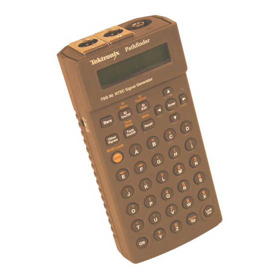
- Page 1 Service Manual TSG 90 PATHFINDER NTSC Signal Generator 070-8706-01 Warning The servicing instructions are for use by qualified personnel only. To avoid personal injury, do not perform any servicing unless you are qualified to do so. Refer to all safety summaries prior to performing service.
- Page 2 Copyright Tektronix, Inc. All rights reserved. Tektronix products are covered by U.S. and foreign patents, issued and pending. Information in this publication supercedes that in all previously published material. Specifications and price change privileges reserved. Tektronix, Inc., P.O. Box 500, Beaverton, Oregon 97077...
-
Page 3: Warranty
product. - Page 4 TSG 90 PATHFINDER Service Manual...
-
Page 5: Table Of Contents
Contents Warranty ..........List of Figures . - Page 6 Contents Diagnostics ..........4–4 Diagnostic Menu .
- Page 7 Contents Table 1–4: Audio Tone ........1–7 Table 1–5: Power Supply .
-
Page 8: Safety Summary
Safety Summary This summary contains general safety information for operating and servicing personnel. Specific warnings and cautions are given throughout the manual where they apply, but may not appear in this summary. Terms In this manual CAUTION statements identify conditions or practices that can damage the equipment or other property. -
Page 9: Power Source
Safety Summary Power Source This product is intended to operate from a power source that applies no more than 250 volts RMS between the supply conductors or between either supply conductor and ground. Ground the product This product is grounded through the grounding conductor of the power module power cord. - Page 10 viii TSG 90 PATHFINDER Service Manual...
-
Page 11: Specifications
Specifications... -
Page 13: Introduction
The following documents were used as references in the preparation of this spec- ification: Product Classification Environmental Test Summary, 13 June 1977; Tektronix Standard 062-2853-00 Electromagnetic Compatibility Environmental Test, 31 March 1977; Tektronix Standard 062-2866-00 Recommendations and reports of the CCIR, 1978; Transmission of Sound Broadcasting and Television Signals Over Long Distances (CMTT) IEEE Standard Dictionary of Electrical Terms, Second Edition (1977);... -
Page 14: Performance Conditions
Specifications Performance Conditions The Performance Requirements are valid within the environmental limits shown in Table 1–7 if the instrument is calibrated in an ambient temperature of 23 C, after a warm-up time of 20 minutes. Safety Standards The following safety standards apply to the TSG 90: ANSI/ISA-S82.01 IEC 348 CAN/CSA C22.2 No. -
Page 15: Specification Tables
Specifications Specification Tables Table 1–1: General Video Test Signal Characteristics Characteristic Performance Requirements Supplemental Information Luminance Amplitude Accuracy 1% of 714.3 mV (100 1 IRE) Chrominance-to-Luminance Gain 2% of 714.3 mV (100 2 IRE) 1% typical. Blanking Level 0 V 50 mV Rise Time Accuracy Except where otherwise specified Burst Amplitude... -
Page 16: Table 1-2: Video Test Signals
Specifications Table 1–2: Video Test Signals Characteristic Performance Information SMPTE Bars See Figure 1–1 Rise Times Luminance 140 ns 25 ns Chrominance –I 250 ns 25 ns 833 ns 80 ns Field Timing Color Bars Lines 21–182; See Figure 1–1a Reverse Blue Bars Lines 183–202;... - Page 17 Specifications Table 1–2: (Cont.)Video Test Signals Characteristic Performance Information Field Square Wave See Figure 1–9 Field Timing Lines (White) Lines 70–213 Lines at Blanking All remaining active lines Amplitude 714.3 mV (100 IRE) Multiburst See Figure 1–10 Amplitudes White Reference Bar 500 mV (70 IRE) Packets 428.6 mV...
-
Page 18: Table 1-3: Character Identification
Specifications Table 1–2: (Cont.)Video Test Signals Characteristic Performance Information All Other Packets 400 ns typical (sine-squared shaped packets) Modulated Pedestal Pedestal Amplitude 357.2 mV (50 IRE) Chrominance Amplitudes 142.9 mV (20 IRE), 285.7 mV (40 IRE), and 571.4 mV (80 IRE) Phase Rise Time 400 ns 40 ns... -
Page 19: Table 1-4: Audio Tone
Specifications Table 1–4: Audio Tone Characteristic Performance Requirements Supplemental Information 0, +4, or +8 dBu into 600 Ω Amplitude Amplitude Accuracy 0.25 dBu Frequency 50, 63, 125, 250, and 400 Hz; 1, 2, 4, 8, 10, 12.5, 16, and 20 kHz; Sweep Frequency Accuracy 0.5 Hz Sweep... -
Page 20: Table 1-7: Environmental Characteristics
Specifications Table 1–7: Environmental Characteristics Characteristic Performance Information Temperature Operating 0 C to +50 C (32 to +122 F) Storage –30 C to +65 C (–22 to +149 F), excluding batteries Altitude Operating (battery) to 15,000 feet (4572 m) Operating (with AC adapter) to 14,000 feet (4267 m) Storage to 50,000 feet (15420 m) -
Page 21: Waveform Illustrations
Specifications Waveform Illustrations Figure 1–1: SMPTE Color Bar Components 1–9 TSG 90 PATHFINDER Service Manual... -
Page 22: Figure 1-2: 75% Color Bars
Specifications Figure 1–2: 75% Color Bars Figure 1–3: Red Field 1–10 TSG 90 PATHFINDER Service Manual... -
Page 23: Figure 1-4: Sin(X)/X
Specifications Figure 1–4: SIN(X)/X Figure 1–5: 5-Step Staircase (Gray Scale) 1–11 TSG 90 PATHFINDER Service Manual... -
Page 24: Figure 1-6: 0 Ire Flat Field
Specifications Figure 1–6: 0 IRE Flat Field Figure 1–7: 50 IRE Flat Field 1–12 TSG 90 PATHFINDER Service Manual... -
Page 25: Figure 1-8: Black Burst
Specifications Figure 1–8: Black Burst Figure 1–9: Field Square Wave 1–13 TSG 90 PATHFINDER Service Manual... -
Page 26: Figure 1-10: Multiburst
Specifications Figure 1–10: Multiburst Figure 1–11: Convergence Components 1–14 TSG 90 PATHFINDER Service Manual... -
Page 27: Figure 1-12: Ntc7 Composite
Specifications Figure 1–12: NTC7 Composite Figure 1–13: NTC7 Combination 1–15 TSG 90 PATHFINDER Service Manual... -
Page 28: Figure 1-14: Fcc Composite
Specifications Figure 1–14: FCC Composite Figure 1–15: Matrix 1–16 TSG 90 PATHFINDER Service Manual... -
Page 29: Figure 1-16: Safe Area
Specifications Figure 1–16: Safe Area 1–17 TSG 90 PATHFINDER Service Manual... - Page 30 1–18 TSG 90 PATHFINDER Service Manual...
-
Page 31: Operating Information
Operating Information... - Page 33 Operating Information The TEKTRONIX TSG 90 PATHFINDER TV Signal Generator is designed for ease of operation and outstanding portability. It provides a complement of 16 NTSC test signals, including the Safe Area signal. It also provides 13 selectable audio frequencies from 50 Hz to 20 kHz, a 50 Hz to 20 kHz audio sweep, and an audio click channel ID.
-
Page 34: Controls, Indicators, And Connectors
Operating Information is provided for the NiCad battery pack only. If eight AA NiCad batteries are used, a separate charger must be provided. Controls, Indicators, and Connectors Controls The controls for the PATHFINDER consists of a keypad, which has buttons to make operational selections and entering menus;... -
Page 35: Lockout
Operating Information Lockout. The Lockout button is used to disable the keypad. While locked out, pressing any key (except Lock Out or ON) produces the message press Lock Out on the LCD display and has no other effect. While in Lock Out mode, a lock symbol (padlock icon) appears in the lower right corner of the LCD display. -
Page 36: Id Edit And Id Position
Operating Information button. The ID Menu allows the ID cycle to be turned on or off, sets the display time for the captions, and selects which of the stored ID messages to cycle in what order. ID Edit and ID Position. Pressing the ID Edit button enters a mode where the current ID text can be edited. -
Page 37: Indicators
Operating Information Indicators All functions of the PATHFINDER are indicated by the LCD display. This back- lit display has two 16-character lines, to display all information necessary for operation, signal selection, text editing, selecting and positioning text messages, and making menu selections. Connectors The PATHFINDER has four connectors: one 75Ω... - Page 38 Operating Information 2–6 TSG 90 PATHFINDER Service Manual...
-
Page 39: Performance Verification And Adjustment Procedures
Performance Verification and Adjustment Procedures... -
Page 41: Required Test Equipment
Table 3–1: Required Test Equipment Item Information/Requirements Example NTSC Video Measurement For measuring and displaying Tektronix 1780 Video Mea- line- and field-rate waveforms. surement Set. Must be capable of making differential phase and gain measurements. Frequency Counter Must be accurate to within 2.5... -
Page 42: Performance Verification Checklist
PATHFIND- ER audio output: Pin 1, shield; pin 2, +; and pin 3, –. Noise Measurement Filter Continuous random noise, 5 Tektronix p/n 015-0213-00. MHz, low-pass filter. BNC Coaxial Cables 75 impedance. (Qty 2) Tektronix p/n 012-0074-00. -
Page 43: Audio Outputs
Performance Verification and Adjustment Procedures 5. Check 5-Step Linearity Max diff step difference <1% 6. Check Luminance Amplitude Accuracy 714 mV 7.14 mV (100 IRE 1 IRE) 7. Check Rise Time 140 ns 20 ns, 10% to 90% 8. Check SCH Phase SCH Phase = 0 9. -
Page 44: Performance Verification Procedures
Performance Verification and Adjustment Procedures Performance Verification Procedures Oscillator Frequency NOTE. After initial delivery or long storage, allow a two-hour warm-up time to re-age the crystal. Thereafter, a 20 minute warm-up time is sufficient. 1. Check Subcarrier Frequency a. Connect the PATHFINDER Video Output to the genlock input of the NTSC Test Signal Generator with a 75Ω... - Page 45 Performance Verification and Adjustment Procedures 4. Check Burst Amplitude a. Using the 1780 WFM + CAL function, match the top of the burst on the lower displayed waveform to the bottom of the burst on the upper waveform. b. CHECK — that the burst amplitude is 285.7 mV 5.7 mV (40 IRE 0.8 IRE).
-
Page 46: Audio Outputs
Performance Verification and Adjustment Procedures 10. Check K–Factor a. With the NTC7 Composite signal still displayed, set the 1780 for K–Factor measurement. b. CHECK — that the PATHFINDER K–Factor is 0.5%. 11. Check Differential Phase and Gain a. Set the 1780 Vectorscope mode to measure differential phase. Use the double trace method, if possible. - Page 47 Performance Verification and Adjustment Procedures b. Set the distortion analyzer to measure THD. c. Set the Tone Frequency, Amplitude, and ID Click with these steps: Open the Tone Menu by pressing SHIFT–TONE ON/OFF (press the two keys simultaneously). Use the keys to set the TONE FREQ to 50 Hz.
- Page 48 Performance Verification and Adjustment Procedures b. CHECK — that the Audio Output is 0 dBu 0.25 dBu. c. Set the PATHFINDER Audio Level to +4 dBu (use the keys). d. CHECK — that the Audio Output is +4 dBu 0.25 dBu. e.
-
Page 49: Adjustment Checklist
Performance Verification and Adjustment Procedures m. Reset the PATHFINDER Tone Frequency, Amplitude, and Click to their normal operating (pre-step 15) states. Adjustment Checklist Use the following checklist if you are familiar with TSG 90 operation and adjust- ment. Step–by–step instructions for all of the procedures begin on the next page. 1. -
Page 50: Adjustment Procedures
Performance Verification and Adjustment Procedures Adjustment Procedures Remove the PATHFINDER back cover before proceeding; see the instructions on page 4–5. Power the instrument with the AC adapter while making adjustments. 1. Adjust Subcarrier Frequency a. Connect the PATHFINDER Video Output to the NTSC Test Signal Generator genlock input with a 75Ω... - Page 51 Performance Verification and Adjustment Procedures c. Enter the diagnostic menu and go to TONE LVL0 with these steps: Turn the PATHFINDER OFF and then ON while holding the LOCKOUT button down. Press the key repeatedly to reach the TONE LVL0 selection (menu item 5).
- Page 52 Performance Verification and Adjustment Procedures a. Select the Multiburst signal from the PATHFINDER (press C). b. Set the 1780 to view all of the multiburst packets on a line. c. ADJUST — L4, L5, L6, L7, and L8 to make the frequency packets flat, and equal amplitude from one packet to another.
-
Page 53: Maintenance
Maintenance... -
Page 55: Battery Hints
Battery Hints For optimal battery life and capacity, use the rechargeable NiCad battery pack (Tektronix p/n 119–4488–00) in full charge/discharge cycles. In other words, ful- ly discharge the battery pack before recharging, and then charge the battery pack until fully charged, approximately 16 hours. A new battery pack will take a few charge/discharge cycles to reach full capacity. -
Page 56: Static-Sensitive Components
Maintenance Static-Sensitive The PATHFINDER contains electrical components that are susceptible to dam- Components age from static discharge. Static voltages of 1 kV to 30 kV are common in un- protected environments. CAUTION. Static discharge can damage any semiconductor component in this instrument. -
Page 57: Diagrams
The circuit board assemblies are assigned assembly numbers starting with A1. Circuit boards have been assigned an assembly number so that they may be or- dered from Tektronix, Inc. They are as follows: A1 Main Board Assembly A2 Keypad Board Assembly... -
Page 58: Diagnostics
Maintenance Diagnostics The PATHFINDER contains no automated diagnostic routines. There is one diagnostic selection found in the diagnostics menu: LCD Diag. This menu is ac- cessed by holding the LOCKOUT button down while turning the PATHFINDER Diagnostic Menu AUTO POWER DOWN Use the keys to enable/disable the Auto Power Down function. -
Page 59: Corrective Maintenance
Corrective maintenance deals with obtaining replacement parts, torque specifica- tions, and component replacement. Obtaining Replacement Replacement parts are available from or through the local Tektronix, Inc., field office or representative. Parts When ordering parts be sure to include the following information in your order: 1. -
Page 60: Connector Panel Removal And Replacement
Maintenance Connector Panel Follow this procedure to remove and replace the connector (“rear”) panel of the PATHFINDER: Removal and Replacement 1. With the back cover removed, disconnect the VIDEO and both AUDIO connector cables from J7, J8, and J9. Again, pull on the connector housing, not on the wires. - Page 61 Maintenance 4. Holding the keypad and Keypad board with the buttons up, slide the front case onto them, aligning the rubber buttons with the holes for them in the front case as you do so. The Keypad board is a friction fit in the front case half, so you must apply some slight pressure to fully seat the assemblies into the case.
- Page 62 4–8 TSG 90 PATHFINDER Service Manual...
-
Page 63: Replaceable Electrical Parts List
Replaceable Electrical Parts... - Page 65 TSG 90. Use this list to identify and order replacement parts. There is a separate Replaceable Electrical Parts list for each instrument. Parts Ordering Information Replacement parts are available from or through your local Tektronix, Inc., Field Office or representative. Changes to Tektronix instruments are sometimes made to accommodate improved components as they become available and to give you the benifit of the latest circuit improvements.
- Page 66 Chassis-mounted parts and cable assemblies have no assembly number prefix and are located at the end of the electrical parts list. Tektronix Part No. Indicates part number to be used when ordering replacement part from (Column 2) Tektronix.
- Page 67 SUB TRACOR INC 78189 ILLINOIS TOOL WORKS INC ST CHARLES ROAD ELGIN IL 60120 SHAKEPROOF DIV 80009 TEKTRONIX INC 14150 SW KARL BRAUN DR BEAVERTON OR 97077–0001 PO BOX 500 91637 DALE ELECTRONICS INC 2064 12TH AVE COLUMBUS NE 68601–3632...
- Page 68 Replaceable Electrical Parts Component Tektronix Serial / Assembly Number Mfr. Mfr. Part Number Part Number Effective Discontinued Name & Description Code Number 671–2585–00 B010100 B010456 CIRCUIT BD ASSY:MAIN 80009 671–2585–00 671–2585–01 B010457 B020729 CIRCUIT BD ASSY:MAIN 80009 671–2585–01 671–2585–02 B020730...
- Page 69 Replaceable Electrical Parts Component Tektronix Serial / Assembly Number Mfr. Mfr. Part Number Part Number Effective Discontinued Name & Description Code Number A1C17 283–5114–00 CAP,FXD,CER:MLC;0.1UF,10%,50V,X7R,1206;SMD, 04222 12065C104KAT1A 8MM T&R A1C18 283–5114–00 CAP,FXD,CER:MLC;0.1UF,10%,50V,X7R,1206;SMD, 04222 12065C104KAT1A 8MM T&R A1C29 283–5114–00 CAP,FXD,CER:MLC;0.1UF,10%,50V,X7R,1206;SMD, 04222 12065C104KAT1A 8MM T&R...
- Page 70 Replaceable Electrical Parts Component Tektronix Serial / Assembly Number Mfr. Mfr. Part Number Part Number Effective Discontinued Name & Description Code Number A1CR4 152–5027–00 DIO,RECT:SCHTKY;40V,1A;MBRS140,SMB J– 80009 152–5027–00 LEAD,12MM TR A1CR15 152–0141–02 671–2585–00 671–2585–01 DIO,SIG:ULTRA 80009 152–0141–02 FAST;40V,150MA,4NS,2PF;1N4152,DO–35,T&R A1CR15 152–0141–02 671–2896–00...
- Page 71 Replaceable Electrical Parts Component Tektronix Serial / Assembly Number Mfr. Mfr. Part Number Part Number Effective Discontinued Name & Description Code Number A1Q5 151–5066–00 XSTR,SIG:MOS,N–CH;60V,0.115A,7.5 80009 151–5066–00 OHM;2N7002,TO–236/SOT–23,8MM T&R A1Q6 151–5044–00 XSTR,PWR:BIPOLAR,PNP;100V,3.0A,3.0MHZ, 04713 MJD32RL AMPL;MJD32C,TO–252/DPAK,16MM T&R A1R1 311–5036–00 RES,VAR,TRMR:CERMET;5K 80009 311–5036–00...
- Page 72 Replaceable Electrical Parts Component Tektronix Serial / Assembly Number Mfr. Mfr. Part Number Part Number Effective Discontinued Name & Description Code Number A1R33 321–5023–00 RES,FXD:THK FILM;2.74K 80009 321–5023–00 OHM,1%,0.125W,TC=100 PPM;1206,T&R A1R34 321–5023–00 RES,FXD:THK FILM;2.74K 80009 321–5023–00 OHM,1%,0.125W,TC=100 PPM;1206,T&R A1R35 321–5027–00 RES,FXD:THK FILM;5.62K...
- Page 73 Replaceable Electrical Parts Component Tektronix Serial / Assembly Number Mfr. Mfr. Part Number Part Number Effective Discontinued Name & Description Code Number A1R53 311–5038–00 671–2585–00 671–2585–03 RES,VAR,TRMR:CERMET;20K 80009 311–5038–00 OHM,25%,0.25W,4MM SQ,TOP ADJ;SMD,T&R A1R53 311–5040–00 671–2585–04 RES,VAR,TRMR:CERMET;10K 32997 3314J–1–103E OHM,25%,0.25W,4MM SQ,TOP ADJ;SMD,T&R A1R53 311–5038–00...
- Page 74 Replaceable Electrical Parts Component Tektronix Serial / Assembly Number Mfr. Mfr. Part Number Part Number Effective Discontinued Name & Description Code Number A1U22 156–5076–00 IC,DGTL:CMOS,FLIP FLOP;DUAL D– 80009 156–5076–00 TYPE;4013B,SO14.150,TUBE A1Y1 119–4503–00 OSC:14.31818MHZ 80009 119–4503–00 671–2586–00 B010100 B021651 CIRCUIT BD ASSY:KEYBOARD 80009 671–2586–00...
-
Page 75: Diagrams/Circuit Board Illustrations
Diagrams/Circuit Board Illustrations... - Page 77 Example: ID CONTROL, (ID CONTROL), or /ID CONTROL. Abbreviations are based on ANSI Y1.1–1972. Other ANSI standards that are used in the preparation of diagrams by Tektronix, Inc. are: Y14.15, 1966 — Drafting Practices. Y14.2, 1973 — Line Conventions and Lettering.
- Page 78 Diagrams/Circuit Board Illustrations The following information and special symbols may appear in this manual. Assembly Numbers Each assembly in the instrument is assigned an assembly number (e.g., A20). The assembly number appears on the diagram (in circuit board outline), circuit board illustration title, and lookup table for the schematic diagram.
- Page 79 Diagrams/Circuit Board Illustrations 6–3 TSG 90...
- Page 80 Diagrams/Circuit Board Illustrations Schematic Diagram <1> Key Board Component Locator Chart The schematic diagram has an alpha-numeric grid to assist in locating parts within that diagram. Assembly A2. 6–4 TSG 90...
- Page 81 TSG 90 KEY BOARD...
- Page 82 Static Sensitive Devices See Maintenance Section A1 MAIN BOARD (Partial Assembly A1 also shown on schematic < 2 >) The schematic diagram has an alpha-numeric grid to assist in locating parts within that diagram. U13A U13B R63** U17A U17B U21A U21B U21C U21D...
- Page 83 TSG 90 CPU, CLOCK, TIMING, DIGITAL AND ID GENERATION...
- Page 84 Schematic Diagram < 2 > Main Board Component Locator Chart The schematic diagram has an alpha-numeric grid to assist in locating parts within that diagram. Assembly A1. Partial Assembly A1 also shown on Schematic < 1 >. R63** TP10 TP11 TP12 U13A U13B...
- Page 85 TSG 90 TEST SIGNAL AND AUDIO OUT, POWER SUPPLY...
- Page 87 Replaceable Mechanical Parts...
-
Page 89: Replaceable Mechanical Parts List
TSG 90. Use this list to identify and order replacement parts. There is a separate Replaceable Mechanical Parts list for each instrument. Parts Ordering Information Replacement parts are available from or through your local Tektronix, Inc., Field Office or representative. Changes to Tektronix instruments are sometimes made to accommodate improved components as they become available and to give you the benifit of the latest circuit improvements. - Page 90 Figure & Index No. Items in this section are referenced by figure and index numbers to the illustra- (Column 1) tions. Tektronix Part No. Indicates part number to be used when ordering replacement part from (Column 2) Tektronix. Serial No.
- Page 91 9301 ALLEN DR CLEVELAND OH 44125–4632 73743 FISCHER SPECIAL MFG CO 111 INDUSTRIAL RD COLD SPRING KY 41076–9749 80009 TEKTRONIX INC 14150 SW KARL BRAUN DR BEAVERTON OR 97077–0001 PO BOX 500 93907 TEXTRON INC 600 18TH AVE ROCKFORD IL 61108–5181 CAMCAR DIV 7–3...
- Page 92 Replaceable Mechanical Parts 1–1 614–0913–00 KIT ASSEMBLY:BATTERY HOLDER SUB ASSEMBLY 80009 614–0913–00 *MOUNTING PARTS* –2 211–0097–00 SCREW,MACHINE:4–40 X 0.312,PNH,STL 93907 ORDER BY DESCR *END MOUNTING PARTS* –3 348–1347–00 PAD,CUSHIONING:TSG90 80009 348–1347–00 –4 200–4075–00 DOOR,BATTERY:POLYCARBONATE 80009 200–4075–00 –5 333–4065–00 PANEL,REAR:POLYCARBONATE 80009 333–4065–00 –6 131–0955–03...
- Page 93 7–5 TSG 90 PATHFINDER Service Manual...
- Page 94 7–6 TSG 90 PATHFINDER Service Manual...
Need help?
Do you have a question about the PATHFINDER TSG 90 and is the answer not in the manual?
Questions and answers