
Related Manuals for Astralpool NARBONNE


Summary of Contents for Astralpool NARBONNE
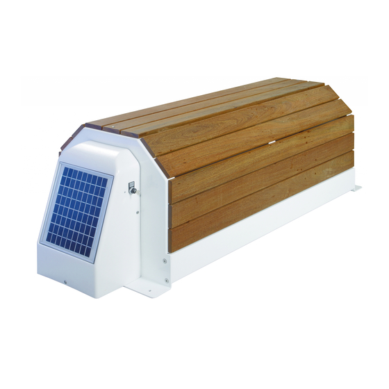
- Page 1 ENGLISH ABOVE-GROUND AUTOMATIC POOL COVER NARBONNE MODEL INSTALLATION AND MAINTENANCE MANUAL Serial N°: Revision number: B007-2012-10-05...
-
Page 2: Table Of Contents
ENGLISH TABLE OF CONTENTS UNLOADING ......................2 TOOLS REQUIRED FOR ASSEMBLY ............... 2 COMPONENTS OF THE AUTOMATIC POOL COVER ..........3 POSITIONING WITH SHARP CORNERS ..............4 POSITIONING WITH RAYS ..................4 ROLLER INSTALLATION ................... 5 SLATS ASSEMBLY ....................7 SLATS DIRECTION.................... -
Page 3: Unloading
ENGLISH UNLOADING TOOLS REQUIRED FOR ASSEMBLY Drill and drill bits for concrete Ø 6 and Ø10 Flat head screwdrivers Phillips screwdrivers Spirit level 10 - 13 – 17 wrench Nippers Wire strippers 5 and 6 mm Allen wrench Hammer Standard and long (10 m) measuring tape Grease Metal saw Grinder with material disk... -
Page 4: Components Of The Automatic Pool Cover
ENGLISH COMPONENTS OF THE AUTOMATIC POOL COVER 1 Structure PVC or WOOD (Shaft assembled on the structure): Roller Shaft Slats and fixing Brackets assembly Electrical box Installation Instructions Operation, care, winterising and maintenance instructions. 3/17 Revision number B-007-2012-10-05... -
Page 5: Positioning With Sharp Corners
ENGLISH POSITIONING WITH SHARP CORNERS "Cut" "Dimension X according to table Sharp corner POSITIONING WITH RAYS "Cut" Dimension X according to table Coping stone rays POOL LENGTH Pool slats length 10 m 12 m Dimension X in mm Dimension X: Cut a piece of coping stone of variable length according to the diameter of slat roller, upon the roller shaft. -
Page 6: Roller Installation
ENGLISH ROLLER INSTALLATION - Position the roller as indicated in the diagram, making sure it is properly centred with respect to the pool. It must be perfectly horizontal when installed (diagonals dimensions). - If there are rays, the roller should be pushed forward to the pool to enable the slats to lower properly in its full width. - Page 7 ENGLISH 6/17 Revision number B-007-2012-10-05...
-
Page 8: Slats Assembly
ENGLISH SLATS ASSEMBLY * Immediately after taking the slats out of the packaging, they should be put into the water to prevent any possible deformation. *The number of slats has been determined according to the length of the pool, though there are 4 extra slats. * The first set of slats is easily recognisable as it has the straps to be fastening to the roller. -
Page 9: Slats Direction
ENGLISH SLATS DIRECTION * Identify the upper side of the slats (curved side). * Identify the slats direction: - Wing to the stair - Groove to the roller shaft Stair Side Roller shaft Side Slat Side on the water SLATS ASSEMBLING Phase 1: Join the slats Phase 2: Join the wing to the groove Phase 3: Move both slats down... -
Page 10: Stair Setting
ENGLISH STAIR SETTING ALLOWED POOL DIMENSION X COVER 1°) Put the stair slats on the water 2°) Assemble the slats until the stairs are completely assembled. 3°) Centre the big width slats in the pool (allowed dimension X: from both sides of the pool) 4°) Centre the stair using this slat. -
Page 11: Electrical Connections
ENGLISH ELECTRICAL CONNECTIONS The electric installation must be made in accordance with C15100 and P91C by a properly trained and qualified electrician. Note : in Presence of an electrolysis in salt the information contact 3 and 4 (contact closed = pool cover closed) will be connected avoid up-chloration to the water’s swimming pool (See the electrolysis’s documentation for wiring) -
Page 12: Plan Of Wiring
ENGLISH PLAN OF WIRING Attention ! Wiring in the case of an electrolysis in salt ! Power cable 2×4² to 15m 2×6² to 15 at 25m 2×10² to 25 at 50m Circuit breaker of 30 mA not included Electric cable 3×... -
Page 13: Limit Switch Adjustment
ENGLISH LIMIT SWITCH ADJUSTMENT Adjustment screwdriver Adjustment screw Adjust the limit switch, staring with the cover completely extended over the pool. Adjustment of cover opening: 1: Turn the switch key to rolling-up position and check the rotational direction of the motor. -
Page 14: Bracket And Strap Position
ENGLISH BRACKET AND STRAP POSITION Warning: The position of the brackets is subject to the position of the skimmers in the pool. If these lasts bother the positioning of the safety Brackets, the positioning of the Brackets will be done taking into account the safety Brackets on the slats panels (If necessary move the straps) POSITION OF BRACKETS AND THE STRAPS FOR THE CAPCIR MODEL... -
Page 15: Safety Brackets Positioning
ENGLISH SAFETY BRACKETS POSITIONING: ABS BRACKETS: 1) When positioning the brackets make sure the shaft of the brackets is placed at 500 mm from 2) Pin the supports. Put the strap between the the edge of the pool. fixation plate and the bracket and keep the strap tense. - Page 16 ENGLISH Inox Bracket for model under construction + screws: 1) When positioning the safety brackets, 2) Put the pin M8 in the Ø10 wholes. The shaft of the brackets must be put at Screw until complete closing of the brackets. 500 mm from the edge of the pool.
- Page 17 ENGLISH ABS brackets INOX support: 1) When placing the safety brackets, The shaft of the brackets must be placed at 500 mm from the edge of the pool. 500mm 2) Screw the supports. Put the strap through the fixation plate and the strap.
- Page 18 ENGLISH 17/17 Revision number B-007-2012-10-05...
- Page 19 ENGLISH www.astralpool.com WE RESERVE THE RIGHT TO CHANGE ALL OR PART OF THE FEATURES OF ARTICLES OR CONTENTS OF THIS DOCUMENT, WITHOUT PRIOR NOTICE 18/17 Revision number B-007-2012-10-05...
Need help?
Do you have a question about the NARBONNE and is the answer not in the manual?
Questions and answers