Advertisement
Quick Links
Advertisement

Summary of Contents for Asus Aaeon UP-CORE
- Page 1 UP-CORE Quick Installation Guide - 1 -...
- Page 2 REVISION HISTORY Revision Date Comments R.0.1 2016/12/26 Initial version - 2 -...
- Page 3 Table of Content 1. UP-CORE Board Layout……………..………….……..…….…………..……..4 2. Connector, Switch References……………………………………….……..….…6 3. Switch Settings……………………………………………….……………………..…..7 4. Connector Pin Assignments…………………………………..………………..7 - 3 -...
-
Page 4: Up-Core Board Layout
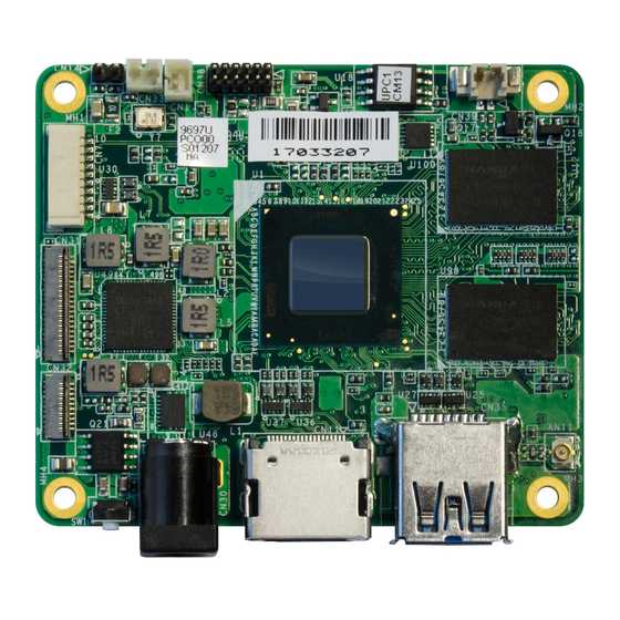
1. UP-CORE Board Layout - 4 -... - Page 5 - 5 -...
-
Page 6: Connector, Switch References
Connector, Switch References Connector Index Reference Functional Description Connector Type Designation Power Button (TF) Push Button Switch.HCH.PTS-099 RTC Battery Wafer (TF) WAFER BOX 2P.180D.1.25mm.CATCH.1201-700-02S CN31 MIPI DSI Connector (TF)FPC/FFC Conn.41P.90D(F).0.6mm.Hirose.FH35C-41S-0.3SHW(50) CN32 MIPI CSI Connector (TF)FPC/FFC Conn.21P.90D(F).0.6mm.Hirose.FH35C-21S-0.3SHW(50) (TF)USB3.0 CONN..9P.90D(F).Sinking.SMD.Single CN35 USB 3.0 Connector Port.TRONTEK.930-00153-A91-21 USB 2.0 1x10P Wafer (TF)Wafer Box.10P.90D.1.0mm.CATCH.1204-700-10RM... -
Page 7: Switch Settings
3. Switch Settings 3.1 SW1: Power Button Switch Position Functional Description SW1 1 (default) SW1 0 Power ON 4. Connector Pin Assignments 4.1 CN1: RTC Battery Wafer www.aaeon.com AAEON Technology Inc. Focus • Agility • Competitiveness... - Page 8 Signal Description +V_COIN_BAT 4.2 CN31: MIPI DSI Connector Signal Description Signal Description Signal Description MDSI_A_DATA1_DN DDI0_TX0_DP DDI0_HPD_CONN DDI0_TX0_DN DDI0_BKLT_R_CTRL MDSI_A_DATA1_DP DDI0_VDD_EN DDI0_TX1_DP DDI0_BKLT_EN MDSI_A_CLK_DN DDI0_TX1_DN MDSI_A_CLK_DP DDI0_TX2_DP +3.3V MDSI_A_DATA0_DN DDI0_TX2_DN +3.3V MDSI_A_DATA0_DP +3.3V DDI0_TX3_DP +3.3V I2C2_3P3_SCL DDI0_TX3_DN +3.3V I2C2_3P3_SDA DDI0_AUX_DP DDI1_DDC_C_CLK DDI0_AUX_DN DDI1_DDC_C_DAT...
- Page 9 Signal Description Signal Description CAM_MCLK MCSI_1_DATA1_DN MCSI_1_DATA1_DP I2C2_SOC_SCL I2C2_SOC_SDA MCSI_1_CLK_DN CAM_RST_N MCSI_1_CLK_DP FLASH_RESET_N +2.8V MCSI_1_DATA0_DN GND_CAM MCSI_1_DATA0_DP +1.2V +1.8V 4.4 CN35: USB 3.0 Connector Signal Description Signal Description CROSSBAR_RX1_P USB2_P1_DN_L USB2_P1_DP_L CROSSBAR_TX1_N CROSSBAR_TX1_P www.aaeon.com AAEON Technology Inc. Focus • Agility • Competitiveness...
- Page 10 CROSSBAR_RX1_N 4.5 CN7: USB 2.0 1x10P Wafer Signal Description Signal Description USB2_P2_DP_L USB2_P3_DN_L USB2_P3_DP_L UART0_RXD UART0_TXD USB2_P2_DN_L 4.6 CN11: HDMI Connector Signal Description Signal Description DDI2_TX0_HDMI_DP+ DDI2_CLK_HDMI_DN- DDI2_TX0_HDMI_DN- HDMI_CEC_D DDI2_TX1_HDMI_DP+ DDI2_DDC_CLK DDI2_TX1_HDMI_DN- DDI2_DDC_DAT DDI2_TX2_HDMI_DP+ +5V_HDMI DDI2_TX2_HDMI_DN- DDI2_TYPE_C_HPD www.aaeon.com -10- AAEON Technology Inc. Focus •...
- Page 11 DDI2_CLK_HDMI_DP+ 4.7 CN14: Reset Pin Header Signal Description PMU_RSTBTN_N 4.8 CN30: DC Jack Signal Description 4.9 CN38: Update CPLD Header Signal Description Signal Description 3.3V FST_SPI_CS0_N FST_SPI_CLK FST_SPI_D1 www.aaeon.com -11- AAEON Technology Inc. Focus • Agility • Competitiveness...
- Page 12 FST_SPI_D0 SPI_SOCK_HOLD_N 4.10 CN33: Power Button Wafer Signal Description PWR_SW#_CTL_R 4.11 CN39: FAN Wafer Signal Description FAN_PWR 4.12 CN34: MIPI CSI CONNECTOR Signal Description Signal Description CAM1_RST_N I2C5_SOC_SDA I2C5_SOC_SCL CAM1_MCLK MCSI_0_DATA0_DN MCSI_0_DATA0_DP MCSI_0_DATA1_DN MCSI_0_DATA1_DP www.aaeon.com -12- AAEON Technology Inc. Focus • Agility • Competitiveness...
- Page 13 MCSI_0_CLK_DN MCSI_0_CLK_DP MCSI_0_DATA2_DN MCSI_0_DATA2_DP MCSI_0_DATA3_DN MCSI_0_DATA3_DP +AVDD_CAM +1.2V +1.8V +2.8V +2.8V 4.13 CN40: EXHAT-100.Header Signal Description Signal Description Signal Description PCIE_REFCLK0_DN ISH_GPIO2 USB_OTG_R_ID ISH_GPIO3 I2C0_SOC_SDA ISH_GPIO4 SD3_CD I2C0_SOC_SCL SD3_CMD ISH_GPIO7 SD3_1P8_EN ISH_GPIO9 I2C1_SOC_SDA LPE_I2S2_CLK PLTRST_BUF_3P3_N SOC_PWM0 SD3_PWREN UART1_RTS LPE_I2S2_FRM I2C1_SOC_SCL PMU_PWRBTN_3P3_N SOC_PWM1 SD3_WP...
- Page 14 USB_HSIC_1_DATA SD3_SD0 UART1_RXD ISH_I2C1_CLK PMC_SUSCLK0 USB_HSIC_1_STROBE SD3_SD1 PCIE_TX0_DP SD3_SD2 DDI2_DDC_CLK PCIE_TX0_DN SPI2_MOSI USB_HSIC_2_DATA SD3_SD3 DDI2_DDC_DAT SPI2_MISO USB_HSIC_2_STROBE HDMI_CEC_D PCIE_RX0_DP SPI2_CLK CPLD_OE HDMI_CEC_R PCIE_RX0_DN SPI2_CS0 USB2_P0_DP CPLD_RST DDI2_TYPE_C_HPD SPI2_CS1 USB2_P0_DN CPLD_STROBE ISH_GPIO0 PCIE_REFCLK0_DP ISH_GPIO1 4.14 ANT1: WIFI Antenna CONNECTOR Signal Description RF trace www.aaeon.com -14-...


Need help?
Do you have a question about the Aaeon UP-CORE and is the answer not in the manual?
Questions and answers