Table of Contents
Advertisement
Quick Links
Advertisement
Table of Contents

Related Manuals for Asus Tinker Board 2 Series


Summary of Contents for Asus Tinker Board 2 Series
- Page 1 Tinker Board 2 Series User Manual...
- Page 2 Circumstances may arise where because of a default on ASUS’ part or other liability, you are entitled to recover damages from ASUS. In each such instance, regardless of the basis on which you are entitled to claim damages from ASUS, ASUS is liable for no more than damages for bodily injury (including death) and damage to real property and tangible personal property;...
-
Page 3: Table Of Contents
Contents Conventions used in this manual ..................................4 Typography ..........................................4 Chapter 1: Specifications Summary 1.1 Introduction ......................................6 1.2 Features ........................................6 1.3 Package contents ....................................6 1.4 Product specification ..................................7 1.5 Dimensions (mm) ....................................8 1.6 Block diagram ......................................8 Chapter 2: Hardware Installation 2.1 Before you proceed ...................................10 2.2 Single board Computer layout ..............................11 2.3 I/O connectors .....................................18 2.3.1... -
Page 4: Conventions Used In This Manual
Where to find more information Refer to the following sources for additional information and for product and software updates. ASUS Websites The ASUS website (https://www.asus.com/) provides updated information on ASUS hardware and software products. Optional Documentation Your product package may include optional documentation, such as warranty flyers, that may have been added by your dealer. -
Page 5: Product Overview
Product Overview... -
Page 6: Introduction
1.1 Introduction Tinker Board 2 Series is more than a dream for the DIY-obsessed: it’s a gateway to new ideas and new relationships. Experienced makers will love Tinker Board’s performance-to-price ratio and strong brand heritage, while novices and younger users will appreciate its accessibility and ease of use. But all will come together to create —... -
Page 7: Product Specification
1.4 Product specification Tinker Board 2 Tinker Board 2S Rockchip RK3399 (64-bit) Dual-core Arm® Cortex®-A72 @ 2.0 GHz Quad-core Arm® Cortex®-A53 @ 1.5 GHz Arm® Mali™-T860 MP4 GPU @ 800 MHz 1 x HDMI™ with CEC hardware ready Display 1 x USB Type-C® (DP 1.2) 1 x 22-pin MIPI DSI (4 lane) supports up to FHD Memory Size Dual-CH LPDDR4 2GB or 4GB... -
Page 8: Dimensions (Mm)
1.5 Dimensions (mm) Front Left Right Rear 1.6 Block diagram Single Board Computer... -
Page 9: Product Introduction
Product Introduction... -
Page 10: Before You Proceed
2.1 Before you proceed Take note of the following precautions before you install your Single Board Computer components or change any single board computer settings. NOTE: The diagrams in this chapter are for reference only. The Single Board Computer layout may vary with models. -
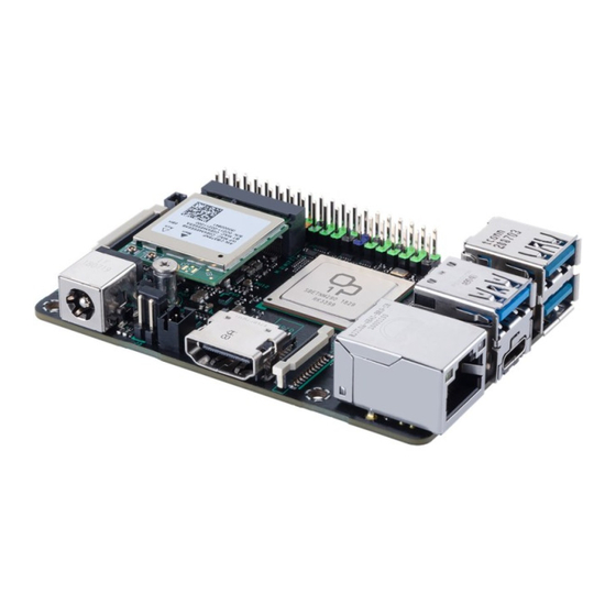
Page 11: Single Board Computer Layout
2.2 Single board Computer layout Top view Bottom view * eMMC is only available on selected models. Layout contents Page GPIO header SOC RK3399 Debug UART header Reset header MIPI DSI connector DC Fan header Power-on header and Maskrom jumper Status LEDs MIPI CSI-2 connector 10. - Page 12 GPIO header This 40-pin GPIO (General-Purpose Input/Output) header can be designated (in software) as an input or output pin and is used for a wide range of purposes. Of the 40 pins, 28 are GPIO pins (shared with SPI/ UART/I2C pins). 40P_GPIO Tinker Board 2 / 2S 40-pins GPIO header Pin definition...
- Page 13 SOC RK3399 This ARM system on a chip (SoC) features the new 64-bit Armv8 architecture and Arm big.LITTLE™ ® ® technology’s 6-core processor, provides improved performance and comes bundled with Arm Mali -T860 ® ® MP4 GPU. Debug UART header This Debug UART header provides a separate UART port, allowing developers to use and develop with the serial console without occupying the 40-pin GPIO’s UART ports.
- Page 14 MIPI DSI connector The MIPI DSI connector is used to connect a MIPI display module via a 4 lane MIPI-DSI cable. This connector supports up to 6 Gbps connection speed. DC Fan header The DC Fan header allows you to connect a fan to actively cool the system. Connector Type JST PH 2P 2.00mm Reference PN:...
- Page 15 Power On header The Power On header allows you to connect an external power button. The Maskrom jumper allows you to mask the eMMC (rom) for recovery. This will allow you to enter developer mode due to the indetected storage and rewrite the eMMC. Dimension 2.54 Status LEDs...
- Page 16 MIPI CSI connector The MIPI CSI connector is used to connect a MIPI camera module via a 2 lane MIPI-CSI2 cable. This connector supports up to 3 Gbps connection speed. WARNING! Ensure the cable for MIPI CSI is connected in the correct orientation with the gold fingers facing towards the rear of the Single Board Computer.
- Page 17 11. M.2 Wi-Fi Slot (E-Key) The M.2 Wi-Fi slot allows you to install an M.2 Wi-Fi module (E-key, type 2230). NOTE: The M.2 Wi-Fi module is purchased separately on selected models. 12. Micro SD Card slot The microSD card slot allows you to install a microSD memory card v2.00 (SDHC) / v3.00 (SDXC) for storage. WARNING! Disconnect all power (including redundant PSUs) from the existing system before you add or remove a memory card, then reboot the system to access the memory card.
-
Page 18: I/O Connectors
2.3 I/O connectors 2.3.1 Left panel DC Power Input Jack The supplied power adapter converts AC power to DC power for use with this jack (5.5mm/2.5mm). Power supplied through this jack supplies power to the Single Board Computer. To prevent damage to the Single Board Computer, always use the supplied power adapter. -
Page 19: Rear Panel
2.3.2 Rear panel LAN (RJ-45) port The 8-pin RJ-45 LAN port supports a standard Ethernet cable for connection to a local network. Please refer to the table below for the LED indications. 16.34±0.25 15.75±0.25 13.80±0.25 13.40±0.25 2.00±0.25 Activity Link LED Speed LED ACT/LINK LED SPEED LED... - Page 20 USB 3.2 Gen 1 Type-A port The USB 3.2 Gen 1 (Universal Serial Bus) port provides a transfer rate up to 5 Gbit/s. USB 3.2 Gen 1 Type-C® OTG port This USB Type-C™ (Universal Serial Bus) port provides a transfer rate of up to 5 Gbit/s 13.1 12.5±0.10 16.3...
-
Page 21: Chapter 3: Software Installation
Software Installation... -
Page 22: Booting From External Micro Sd Card
Setting Up: 1. Insert the micro SD card into a Windows® PC. 2. Download the TinkerOS image from the Tinker Board website (https://tinker-board.asus.com/download. html) and burn it into the micro SD card using a third-party ISO software, such as Etcher. -
Page 23: Appendix
Appendix... -
Page 24: Notices
(2) este equipo o dispositivo debe aceptar cualquier interferencia, incluyendo la que pueda causar su operación no deseada. Regional notice for Singapore Complies with This ASUS product complies with IMDA Standards. IMDA Standards DB103778 HDMI Compliance Statement The terms HDMI, HDMI High-Definition Multimedia Interface, and the HDMI Logo are trademarks or registered trademarks of HDMI Licensing Administrator, Inc. -
Page 25: Radio Frequency (Rf) Exposure Information
Compliance Statement of Innovation, Science and Economic Development Canada (ISED) This device complies with Innovation, Science and Economic Development Canada licence exempt RSS standard(s). Operation is subject to the following two conditions: (1) this device may not cause interference, and (2) this device must accept any interference, including interference that may cause undesired operation of the device. - Page 26 NCC: Taiwan Wireless Statement Contains module NCCAI18LP2010T7 經型式認證合格之低功率射頻電機,非經許可,公司、商號或使用者均不得擅自變更頻率、加大功率或 變更原設計之特性及功能。低功率射頻電機之使用不得影響飛航安全及干擾合法通信;經發現有干擾現象 時,應立即停用,並改善至無干擾時方得繼續使用。前項合法通信,指依電信法規定作業之無線電通信。 低功率射頻電機須忍受合法通信或工業、科學及醫療用電波輻射性電機設備之干擾。 VCCI: Japan Compliance Statement Contains module 201-180775 Class B ITE Contains module 00158-19-04076 00158-19-04076 限用物質及其化學符號: 限用物質及其化學符號 單元 鉛 (Pb) 汞 (Hg) 鎘 (Cd) 六價鉻 (Cr ) 多溴聯苯 (PBB) 多溴二苯醚 (PBDE) 印刷電路板及電子組件...
- Page 27 ASUSTek Computer Inc. con la presente dichiara che questo dispositivo è conforme ai requisiti essenziali e alle altre disposizioni pertinenti con la direttiva 2014/53/EU. Il testo completo della dichiarazione di conformità UE è disponibile all’indirizzo: https://www.asus.com/support/ Упрощенное заявление о соответствии европейской директиве...
- Page 28 Spoločnosť ASUSTek Computer Inc. týmto vyhlasuje, že toto zariadenie je v súlade so základnými požiadavkami a ďalšími príslušnými ustanoveniami smernice č. 2014/53/EÚ. Plné znenie vyhlásenia o zhode pre EÚ je k dispozícii na lokalite https://www.asus.com/support/ Poenostavljena izjava EU o skladnosti ASUSTek Computer Inc.
- Page 29 AB uygunluk bildiriminin tam metni şu adreste bulunabilir: https://www.asus.com/support/ Спрощена декларація про відповідність нормам ЄС ASUSTek Computer Inc. заявляє, що цей пристрій відповідає основним вимогам та іншим відповідним вимогам Директиви 2014 / 53 / EU. Повний текст декларації відповідності нормам ЄС доступний на https://www.asus.com/support/ Single Board Computer...
-
Page 30: Fcc Compliance Information
FCC COMPLIANCE INFORMATION Per FCC Part 2 Section 2.1077 Asus Computer International Responsible Party: Address: 48720 Kato Rd, Fremont, CA 94538 Phone/Fax No: (510)739-3777/(510)608-4555 hereby declares that the product Product Name : MOTHERBOARD Model Number : TINKER BOARD 2, TINKER BOARD 2S compliance statement: This device complies with part 15 of the FCC Rules.
Need help?
Do you have a question about the Tinker Board 2 Series and is the answer not in the manual?
Questions and answers