
Subscribe to Our Youtube Channel
Related Manuals for AIC SILOX 140L


Summary of Contents for AIC SILOX 140L
- Page 1 h e a t i n g s y s t e m s installation and maintenance manual FOR THE INSTALLER AND THE USER SILOX 140·180·215·260·400·600·1000 L DOMESTIC HOT WATER STAINLESS STEEL CYLINDERS h e a t i n g s y s t e m s...
- Page 2 CERTIFIED PRODUCT All our models are compliant with: î European Directive 97/23/EEC - Pressure Equipment (art. 3.3). models that can operate with an electric heating element : î European standard EN 60335 - Safety in electrical and similar î European Directive 2006/95/EC - Low Voltage Directive. î...
-
Page 3: Table Of Contents
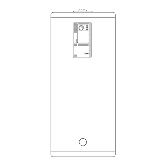
able of onTenTs INDEX OF ILLUSTRATIONS ........4 eneral nformatIon About This Manual ..........4 Fig. 1. Product Description ..........6 General Safety Instructions ........5 Fig. 2. Control Panel Description ........7 ........6 roduct escrIPtIon Fig. 3. Optional DHW Hydraulic Kit ........14 SILOX Cylinders ...........6 Fig. -
Page 4: G Eneral I Nformation
eneral nformatIon About This Manual This documentation is part of the product. It will be handed over to the end-user who will keep it, with all the other applicable documents, in a safe place and readily available for use. Before installing, operating or maintaining the appliance, please carefully read this manual and all the applicable documents provided with the components and accessories. -
Page 5: General Safety Instructions
eneral nformatIon General Safety Instructions When the appliance is con- î nected to the electrical net- work, it must be earthed. This appliance must be installed ac- Make sure that a fuse or circuit breaker î î cording to the applicable local regu- of the recommended rating is installed lations and standards by a qualifi ed outside the appliance, so as to be able... -
Page 6: P Roduct D Escription
The cylinders are installed vertically on the floor and can be connected to various heating sources : boil- AIC’s SILOX water heaters are twin-wall cylinders er, heat pump, solar panels, etc. that are designed for the production and storage of They can also be equipped with an optional elec- Domestic Hot Water. -
Page 7: Control Panel
Please refer to “Hydraulic Kit Characteristics” on page 14 for the characteristics and contact your AIC The control panel contains the required items to representative for more information. control the operation of the optional heating element... -
Page 8: T Echnical S Pecifications
echnIcal PecIfIcatIons Dimensions SX140 to SX600 Recirculation / T&P relief valve installation location Air Vent SX1000 Air Vent Dimensions (mm) SX140 SX180 SX215 SX260 SX400 SX600 SX1000 1,030 1,280 1,530 1,770 1,725 1,730 2,250 1,085 1,335 1,575 1,510 1,490 1,925 —... -
Page 9: Product Data
echnIcal PecIfIcatIons Product Data SX140 SX180 SX215 SX260 SX400 SX600 SX1000 Total water capacity DHW capacity Outer (primary) tank capacity Heat transfer area Max. DHW temperature °C Max. primary temperature °C Operating primary temp. °C T&P valve temperature setting °C 90 - 95 Max. -
Page 10: Recommendations For The Quality Of Water
î ard EN 14868. Copper < 0,1 mg/l An air separator (on the appliance supply AIC recommends to have the DHW circuit î î operating at more than 60°C to prevent the circuit) combined with a dirt separator (up- stream of the appliance) must be installed development of bacteria in the DHW circuit. -
Page 11: G3 Requirements In The Uk
echnical pecificaTionS G3 Requirements in the UK Discharge pipe from safety valves 3.51 The diameter of discharge pipe (D1) should be not less than the nominal outlet size of the tem- The Building Regulation G3 requires that any dis- perature relief valve. charge from an unvented system is conveyed to 3.52 Where a manifold is used it should be sized... - Page 12 echnical pecificaTionS 3.58 The discharge pipe (D2) should be at least Termination of discharge pipe one pipe size larger than the nominal outlet size of 3.61 The discharge pipe (D2) from the tundish the safety device unless its total equivalent hydraulic should terminate in a safe place where there is no resistance exceeds that of a straight pipe 9m long, risk to persons in the vicinity of the discharge.
- Page 13 echnical pecificaTionS temperature relief valve to tundish 600mm maximum Tundish 300mm minimum Discharge below fixed Metal discharge pipe (D2) tundish with grating (3.61 gives continuous fall. See 3.56, Table G3 and alternative points of worked example discharge) Fixed grating Trapped gulley Figure G3: Typical discharge pipe arrangement Maximum resistance Minimum size of dis-...
-
Page 14: Hydraulic Kit Characteristics
echnical pecificaTionS Example of discharge pipe sizing Maximum resistance allowed for a straight length of 28mm pipe (D2) from a G1/2 temperature relief Figure on previous page shows a G1/2 tempera- valves equates to 18m. ture relief valve with a discharge pipe (D2) having Subtract the resistance of 4 No. -
Page 15: Wiring Diagram
echnical pecificaTionS Wiring Diagram For opt. heating element For opt. heating element > 2.5 kW ~230 V > 2.5 kW ~400 V Earth Indicator lights Summer/winter switch Heating element (resistance) Control and safety thermostat TL° : Relay Re : External contactor Pump Connect your motorised spring-closed control valve to terminals 4 &... -
Page 16: P Roduct I Nstallation
roduct nstallatIon Safety Instructions for the Installation The appliance must be in- î stalled in a dry and protect- All connections must be carried out î ed area, with an ambient in accordance with current standards temperature comprised be- and regulations in force. tween 0 and 45°C. -
Page 17: Optional Heating Element Installation
roduct roduct nstallatIon nstallatIon Optional Heating Element Installation Tighten. Conditions: Fill with water: î If the outer tank was emptied for heating el- Outer tank drained as required. Refer to “Draining ement installation, fill the outer tank, refer to the Cylinder” on page 24. “Filling the Cylinder”... -
Page 18: Safety Instructions And Recommendations For The Hydraulic Circuits
The circuit diagrams are theoretical î mended. representations that do not necessarily Consult your AIC representative to deter- î include all the required safety devices. mine the compatibility of the antifreeze Make sure to plan correctly your system... -
Page 19: Hydraulic Connections
roduct nstallatIon Hydraulic Connections Check valve Circulating pump Draw-off tap Expansion vessel Thermostatic mixing valve Relief valve T&P relief valve (UK) (Except SX1000) - See Detail A Isolating valve Check valve Pressure DHW Outlet Cold water inlet reducing valve DHW CIRCUIT From distribution network Detail A... -
Page 20: Silox Cylinder Used As An Electric Water Heater - Typical Connection Diagram
roduct nstallatIon Check valve Circulating pump Draw-off tap Expansion vessel Thermostatic mixing valve Relief valve T&P relief valve (UK) (except SX1000) - See Detail A Isolating valve Check valve Pressure DHW Outlet Cold water inlet reducing valve DHW CIRCUIT From distribution network Detail A h e a t i n g... -
Page 21: C Ommissioning
ommIssIonInG Filling the Cylinder Starting Up Condition(s): Condition(s): Cylinder flushed with fresh water. Start-up procedure: Filling procedure: Switch on and check that the indicator light illuminates. Always fill and pressurise the inner Put Summer/Winter switch to the required tank (DHW) before filling the outer position for operation with an external heat (primary) tank. -
Page 22: Safety Instructions And Recommendations
Inspection mainte- î nance tasks should be car- ried out every 12 months. AIC recommends that the maintenance î Water fl owing out of the drain valve î of the appliance and its components is can be extremely hot. Use extreme carried out by a qualifi ed professional. - Page 23 aintenance Item Action Frequency (times/year) Manual operation safety î Allow cylinder to cool. valves (T&P relief valve and ex- î Slowly twist open the relief valve. pansion vessel relief valve) î Check that water flows freely. î Check that the valve reseats correctly when re- leased.
-
Page 24: Draining The Cylinder
aintenance Draining the Cylinder Always depressurise and/or empty the outer (primary) tank before depressurising and emptying the inner tank (DHW). Failure to comply may damage the inner tank. Draw-off tap Isolating valve (DHW outlet) From distribution network Isolating valve h e a t i n g s y s t e m s DHW draining valve Primary circuit outlet with... -
Page 25: T Roubleshooting
roubleshootInG Problem Cause(s) Solution(s) 1. Make sure the power supply cable is connected to the mains. No power supply 2. Check the external power supply box and reset it as required. Check that the Summer/Winter switch is on Winter position and indicator light Primary circuit from external heat is On. -
Page 26: P Roduct F Iche
Iche Product Fiche AIC SILOX Referring to Commission Delegated Regulation No 812/2013 Model Energy efficiency Standing Volume class loss SX140 49 W 138 lts SX180 53 W 176 lts SX215 56 W 214 lts SX260 61 W 252 lts... - Page 27 otes I10_087-00 • SILOX_EN...
- Page 28 AIC Europe B.V. Graafschap Hornelaan 163A NL-6001 AC Weert The Netherlands www.myaic.eu...
Need help?
Do you have a question about the SILOX 140L and is the answer not in the manual?
Questions and answers