
Subscribe to Our Youtube Channel
Related Manuals for AIC Nesta Series


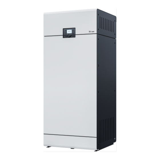
Summary of Contents for AIC Nesta Series
- Page 1 h e a t i n g s y s t e m s installation and maintenance manual FOR THE INSTALLER AND THE USER NESTA 120·160·200·250 kW FLOOR — STANDING CONDENSING BOILER...
-
Page 2: Table Of Contents
able of onTenTs ........G-4 Safety Instructions for the Chimney Connections I-34 eneral nformatIon Chimney Connection ........I-36 Liabilities of the Manufacturer, the Installer Accessories ............. I-36 and the End user ..........G-4 Engineering the Chimney System ....I-37 About this Manual ..........G-5 Safety Instructions for the Electrical Safety Instructions ...........G-6 Connections ............ - Page 3 ndex of llustratIons Fig. 1. Boiler Packaged for Transport ......G-7 Fig. 2. Data Plate - Typical ..........G-7 Fig. 3. Boiler Components - Front and Rear Views ..G-9 Fig. 4. Control Panel ............. G-10 Fig. 5. Typical Display ........... G-11 Fig. 6. Single Boiler Clearances ........
-
Page 4: G Eneral I Nformation
eneral nformatIon Liabilities of the Manufacturer, the Installer and the End user Manufacturer The installer shall provide the end-user with: Any relevant explanation about the op- î Our products are manufactured in compliance eration of the appliance and the heat- with the requirements of the applicable Europe- ing system as well as the safety devices an Directives and standards, and are therefore... -
Page 5: About This Manual
eneral nformatIon About this Manual This documentation is part of the product. It will be handed over to the end-user who will keep it, with all the other applicable documents, in a safe place and readily available for use. Before installing, operating or maintaining the appliance, please carefully read this manual and all the applicable documents provided with the components and accessories. -
Page 6: Safety Instructions
eneral nformatIon Safety Instructions IF YOU SMELL GAS: → DO NOT: → DO: Close the gas supply î Use an open fl ame î Open all doors and windows to î Smoke î ventilate the room î Use electrical devices (phones, î... -
Page 7: G Eneral I Nformation
AIC Europe B.V. Please read installation and The boiler is pre-adjusted in Graafschap Hornelaan 163A... -
Page 8: P Roduct D Escription
Some optional equipment can be used with the The Nesta boilers can be connected in a cascade Nesta boilers. Please contact your AIC Europe rep- configuration, which means that the boilers are resentative for more information and a list of avail- connected to the same water circuit and electronic able equipment. -
Page 9: Fig. 3. Boiler Components - Front And Rear Views
roduct escriPtion Fig. 3. Boiler Components - Front and Rear Views Air inlet duct 16. Control panel with LCD display Fan and burner assembly 17. Burner plate temperature limit switch Ignition electrode 18. Air adapter Hoisting ring 19. Gas valve Water pressure sensor 20. -
Page 10: Control Panel And Main Functions
roduct escriPtion Control Panel and Main Functions Fig. 4. Control Panel Chimney sweep function button - This button allows to Domestic Hot Water on/off button - Pressing this button ac- perform a measurement of the flue gas contents. tivates/deactivates of the Domestic Hot Water function ( Manual operation mode button - The operation de- LCD Display - The display illuminates whenever a control pends on the function defined for the relays (Expert Lev-... -
Page 11: Symbols And Messages On The Control Panel
roduct escriPtion Symbols and Messages on the Control The following symbols are displayed on the screen Panel (See Fig. 5): The following symbols are present on the control ). The time scale ( Comfort mode active ( panel (See Fig. 5): at the bottom of the display indicates the period during which this mode is active (in Domestic Hot Water mode. -
Page 12: T Echnical S Pecifications
echnIcal PecIfIcatIons Dimensions and Clearances 625 mm 648 mm Dimensions & weights N 120 FS N 160 FS N 200 FS N 250 FS 1,320 1,320 1,320 1,320 1,306 1,319 1,308 1,312 1,098 1,098 1,098 1,098 dry weight G-12 A-070336_EN • Rev. A... -
Page 13: Fig. 6. Single Boiler Clearances
echnical pecificaTionS N 120 FS N 200 FS Connections N 160 FS N 250 FS supply/return connections ( ) Ø - [M] safety group connection ( ) Ø - [F] gas connection ( ) Ø - [M] flue gas exhaust connection Ø combustion air inlet connection Ø... -
Page 14: Performance And Efficiency Data
echnical pecificaTionS N 120 FS N 160 FS N 200 FS N 250 FS Performance and Efficiency Data (min. - max.) (min. - max.) (min. - max.) (min. - max.) heat input (net) 11.2 - 115.5 19.0 - 151.4 25.0 - 190.0 17.1- 232.0 heat output at 80/60°C 10.2 - 112.8... -
Page 15: Combustion And Gas Data
echnical pecificaTionS N 120 FS N 160 FS N 200 FS N 250 FS Combustion and Gas Data (min. - max.) (min. - max.) (min. - max.) (min. - max.) chimney type(s) flue gas temperature at 80/60°C °C 52 - 60 55 - 61 54 - 62 55 - 61... -
Page 16: Hydraulic Data
echnical pecificaTionS Hydraulic Data N 120 FS N 160 FS N 200 FS N 250 FS water content hydraulic pressure drop at ∆T = 20k mbar minimum operating pressure maximum operating pressure maximum boiler supply temperature °C Pressure Drop Curve N 200 FS / N 250 FS N 120 FS / N 160 FS... -
Page 17: I Nstructions For The U Ser
nstructIons for the Safety Instructions for the User IF YOU SMELL GAS: → DO: → DO NOT: Close the gas supply î Use an open fl ame î Open all doors and windows to ven- î Smoke î tilate the room î... -
Page 18: Periodic Checks
nstructIons for the Periodic checks If works need to be per- î formed close to the appli- ance (e.g. in the boiler room Check regularly that the wa- or close to the air inlets), î ter pressure of the system is make sure that the appli- at least 1.2 bar when cold. -
Page 19: Starting The Appliance
nstructIons for the Starting the Appliance Stopping the Appliance The first start-up of the boiler after its Conditions: installation must be performed by a None qualified professional, according to the “Start-up and Combus- procedure in Procedure: tion Adjustments” on page I-43. Push the On/Off switch located on the right side of the boiler. -
Page 20: Basic Settings
nstructIons for the Basic Settings Setting Procedure Controls/Screens Press the Heating mode selection button to toggle from one Heating mode mode to the other: selection • Automatic mode ( ) (to be programmed, refer to “Boiler Settings for the Installer” on page I-56. •... - Page 21 nstructIons for the Setting Procedure Controls/Screens Press the OK button (2) to access the end user menu. Times of start and end of Rotate the knob (1) to scroll through the menu until “Time Program heating circuit 1” (5) is highlighted. comfort mode schedule Press the OK button (2) to validate the selection...
- Page 22 nstructIons for the Setting Procedure Controls/Screens Press the OK button (2) to access the end-user menu. Language Selection Rotate the knob (1) to scroll through the menu until “Operator Section” (9) is highlighted. Press the OK button (2) to validate the selection Rotate the knob (1) to select the required language (DE, EN, FR, IT, NL, ES, DA, SV, FI, PT).
-
Page 23: Structure Of Menus For The End User
nstructIons for the Structure of Menus for the End User Some parameters are only visible if the heating circuit is installed Top menu Submenu 1 Submenu 2 Default Time of day and date Hours / Minutes 01:00 (hh:min) Ҙ (Adjust as required) Day / Month 01.01 (dd.mm) Ҙ... - Page 24 nstructIons for the Top menu Submenu 1 Submenu 2 Default Heating circuit 1 Room comfort setpoint 20°C Ҙ Room reduced setpoint 16°C Ҙ Room frost protection 10°C Ҙ setpoint Heating curve slope Ҙ Summer/winter heating limit 18°C Ҙ Flow temp setpoint room 65°C Ҙ...
-
Page 25: P Roduct I Nstallation
roduct nstallatIon Safety Instructions for the Installation When the appliance is con- î nected to the electrical net- All connections (electrical, fl ue pipe, î work, it must be earthed. hydraulic, gas) must be carried out in accordance with current standards Make sure that a fuse or circuit breaker î... -
Page 26: Handling The Product
roduct nstallatIon Handling the Product Move the appliance carefully to its final po- sition. Make sure to comply with the recom- This appliance is heavy and î “Dimensions and mended clearances (See requires sufficient work- Clearances” on page G-12). force to move and handle it, If some height is required for condensate flow as well as an appropriate means of transport. -
Page 27: Removing And Installing The Access Panels
roduct nstallatIon Removing and Installing the Access Panels Top panel Conditions: Push the top panel downwards to engage Tools and Material: the studs into their receptacles. î Wrench, hex head, size 4 Side Panels Removal Procedure: Bottom: install six retained screws. Bottom Front Panel Top : Install four retained screws. -
Page 28: Requirements For The Hydraulic Connections
roduct nstallatIon Requirements for the Hydraulic Connec- tions It is recommended to install î the following devices in the system to prevent water contamination : Make sure that the circuit is provided with Water fi lter and/or dirt separator in- î... -
Page 29: Water Quality Requirements To Prevent Scaling And Corrosion
roduct nstallatIon Water Quality Requirements to Prevent Scaling and Corrosion To prevent the formation of scale and sludge in a Water Hardness closed heating circuit through the penetration of If the hardness of the fi ll water is higher than î... -
Page 30: Typical Hydraulic Connections - Heating Circuit
roduct nstallatIon Typical Hydraulic Connections - Heating Circuit Isolating valve Filling valve Draining valve Check valve Expansion vessel Safety group (automatic air relief valve, manometer, safety valve), con- nected to the drain Circulating pump Removable fi lling hose Drain Fig. 10. Typical Heating System To make maintenance easier, we recommend to remove the plug from the drain connection (see “Fig. -
Page 31: Hydraulic Connections - Cascaded Boilers, With External Domestic Hot Water Tank And Plate Heat Exchanger
roduct nstallatIon Hydraulic Connections - Cascaded boilers, with External Domestic Hot Water Tank and Plate Heat Exchanger Isolating valve Heating circuit pump Filling valve DHW circuit pump Draining valve Check valve Motorised 3-way valve (when needed for low temp systems) Expansion vessel Heating circuit Safety group (automatic air relief valve, manome-... -
Page 32: Hydraulic Connections - Cascaded Boilers, With External Domestic Hot Water Tank And Low Loss Header
roduct nstallatIon Hydraulic Connections - Cascaded boilers, with External Domestic Hot Water Tank and Low Loss Header Isolating valve Heating circuit pump Filling valve DHW circuit pump Draining valve Check valve Motorised 3-way valve (when needed for low temp systems) Expansion vessel Heating circuit Safety group (automatic air relief valve, manome-... -
Page 33: Safety Instructions For The Gas Connection
roduct nstallatIon Safety Instructions for the Gas Connection Check the gas pressure and con- sumption at appliance start up and When connecting the gas circuit, î at each maintenance, and perform make sure to comply with all applica- the adjustment procedure provid- ble local regulations and standards. -
Page 34: Safety Instructions For The Chimney Connections
Please contact In the case of parallel fl ue systems, î your AIC Technical Support make sure to maintain suffi cient dis- for more information. tance (at least 40 mm) between the A condensation outlet connected to the î... - Page 35 roduct nstallatIon Plastic fl ue pipes should be î Flue pipe elements or PP air î allowed to expand under the inlet elements should not be eff ect of heat. Leave about screwed together. 10 mm between the pipe and the sleeve end stop.
-
Page 36: Chimney Connection
In that or cascades), make sure to install case, it may be necessary to install the an AIC-approved flue gas damper floor-standing boiler on a base to get suf- on each boiler in the system. ficient downward flow. If flow is not suffi- cient, install a condensate pump. -
Page 37: Engineering The Chimney System
200 When several boilers need to be connected î Pa (including maximum wind condition) to a common duct, please contact your AIC measured at the outlet of each boiler at Europe representative for more information. maximum output. -
Page 38: Safety Instructions For The Electrical Connections
roduct nstallatIon Safety Instructions for the Electrical Connections Connections Any damaged power supply cable must be replaced using cables as described below and installed by a qualified professional. Electrical connections must be carried The cross-section of the wires should be out by a qualifi... -
Page 39: Accessing The Low Voltage Terminal Strip And Electronic Board
roduct nstallatIon Accessing the Low Voltage Terminal Routing the Cables Strip and Electronic board Conditions: Tools and material: î Wrench, hex head, size 4 Route voltage cables Procedure: Route high through these voltage cables holes “Removing Remove center front panel, see through these holes and Installing the Access Panels”... -
Page 40: Wiring Diagram
roduct nstallatIon Wiring Diagram Signal Signal +24V HALL Signal Signal +24V +15V Signal Signal Signal 1 2 3 4 5 Signal Signal Signal Signal Ionization I-40 A-070336_EN • Rev. A... - Page 41 roduct nstallatIon From Item Terminal No Terminals Remark (Main board) 1(N), 2 (PE), 1 (PE), 2 (N) & On/Off switch X1a (A1) Rear Box (RB) 3 (L) 3 (L) Heating Circuit pump/ X1b (QX) - QX2 2 (N) & 1 (L) Rear Box (RB) 13 (N) &...
-
Page 42: C Ommissioning
ommIssIonInG Safety Instructions Before Start-up Filling the System Conditions: Procedure: Check that all connections (electrical, î fl ue pipe, hydraulic, gas) have been 1. Connect the fi lling hose ( ) to the system carried out and that they are tight and fi... -
Page 43: Start-Up And Combustion Adjustments
ommissioning Start-up and Combustion Adjustments Check CO contents in the flue gas at max output as follows: î Press the Information button ( ). The mod- Conditions: ulation indicator is displayed (in %). Tools and material: î Rotate the knob ( ) to increase to 100% for maximum power. -
Page 44: M Aintenance
aIntenance Safety Instructions for Maintenance The maintenance of the ap- î pliance and its components must be carried out by a qualifi ed professional. Inspection and maintenance tasks î Defective parts and components may î must be carried out by a qualifi ed and only be replaced by genuine factory certifi... -
Page 45: Maintenance Requirements
aintenance Maintenance Requirements @ inspection @ maintenance Tasks (1 year) (2 years max) Check that the boiler room ventilation / boiler air and flue ducts are unobstructed. Verify flue gas and combustion air ducts are in good condi- tion, sealed tight and properly supported. Open the front panel and check the general condition inside the cabinet. -
Page 46: Shutting Down For Maintenance
aintenance Shutting Down for Maintenance Restarting after Maintenance Conditions: Conditions: None Procedure: Procedure: Push in the On/Off switch located on the Push the On/Off switch located on the right side of right side of the boiler. the boiler. When in the On position, the switch re- When in the OFF position, the switch mains pushed in and is illuminated. -
Page 47: Cleaning The Condensate Pipe And Trap
aintenance Cleaning the Condensate Pipe and Trap Remove the cover gasket ( ). Discard. Wipe clean the condensate level switch ( Conditions: attached to the cover. Remove and replace as required. Clean the deposits in the condensate trap ( Tools and material: using clear water and a cloth. -
Page 48: Removing And Installing The Fan And Air Adapter Assembly
aintenance Removing and Installing the Fan and Air Remove the fan gasket ( ). Discard. Adapter Assembly Remove the electrodes, as required, refer to “Removing and Installing the Ignition and Ionization Electrodes” on page I-50. Conditions: Remove the burner, as required, refer to “Removing and Installing the Burner”... - Page 49 aintenance Nesta 120 Nesta 160 - 200 Nesta 250 I-49 A-070336_EN • Rev. A...
-
Page 50: Removing And Installing The Ignition And Ionization Electrodes
aintenance Removing and Installing the Ignition and Release two screws ( ) from the electrode Ionization Electrodes flange. Remove the electrode and screws from the burner plate ( ). Discard, as required. Conditions: Remove electrode gasket ( ) and discard, as Tools and material: required. -
Page 51: Removing And Installing The Burner
aintenance Removing and Installing the Burner Conditions: “Check- Clean the combustion chamber, see ing and Cleaning the Combustion Cham- ber” on page I-52. î Fan and air adapter assembly removed, refer “Removing and Installing the Fan and Air Installation procedure: Adapter Assembly”... -
Page 52: Checking And Cleaning The Combustion Chamber
aintenance Checking and Cleaning the Combustion Cleaning Procedure Chamber Using a nylon bristle brush, sweep the walls Conditions: of the combustion chamber. Using an industrial vacuum cleaner, remove “Removing and Install- î Burner removed, see all deposits from the combustion chamber ing the Burner”... -
Page 53: A Dditional I Nformation For The I Nstaller
ddItIonal nformatIon for the nstaller Optional Modules Additional Heating Circuit Modules & Cable Web Server Module Through the use of this module, you can connect Nesta boilers can control 3 heating circuits with to an Ethernet and get remote access to the boiler mixing functions, using 3 extension modules. -
Page 54: Boilers In A Cascade System
dditionAl nformAtion for the nstAller Boilers in a Cascade System This boiler has all the logic control of the cascaded system and also regulates the stop/start sequence In a heating system comprised of several boilers, it of each boiler according to the demand of the in- is important that the power generated by the boilers stallation. -
Page 55: Fig. 27. Cascade System With Plate Heat Exchanger Low Loss Header
dditionAl nformAtion for the nstAller H.C. – Heating circuit 10. DHW Storage tank D.H.W. – Domestic hot water 11. DHW Storage tank temperature sensor A – Mains cold water supply/drain 12. Check valve B – DHW cold water supply 13. Water pressure sensor Inlet temperature sensor 14. -
Page 56: Boiler Settings For The Installer
dditionAl nformAtion for the nstAller Boiler Settings for the Installer Commissioning Menu Access Levels When starting up the boiler for the first time, a com- missioning screen will come up. It can be exited Three different levels of settings are available for the without adjustments by pressing the ESC ( ) button. - Page 57 dditionAl nformAtion for the nstAller Top menu Level Pgm No. Submenu 1 Submenu 2 Default Setting Operator Operation HC2 Jointly with HC1 Ҙ Ÿ Jointly Section Independently Ÿ with HC1 (Cnt’d) Operation HC3/P Jointly with HC1 Jointly Ҙ Ÿ with HC1 Independently Ÿ...
- Page 58 dditionAl nformAtion for the nstAller Top menu Level Pgm No. Submenu 1 Submenu 2 Default Setting Room comfort setpoint Heating Ҙ 20.0°C circuit 1 Room reduced setpoint Ҙ 16.0°C Room frost protection Ҙ 10.0°C setpoint Comfort setpoint max Ҙ 35.0°C Heating curve slope Ҙ...
- Page 59 dditionAl nformAtion for the nstAller Top menu Level Pgm No. Submenu 1 Submenu 2 Default Setting Excess heat draw Heating cir- Ҙ Ÿ Heating mode Always cuit 1 (Cnt’d) Ÿ Always Ÿ With buffer Ҙ Ÿ Ÿ With prim contr/system Ҙ...
-
Page 60: Error Codes And Solutions
Explanation Action(s) Outside temperature sensor er- Check connection and/or sensor. Replace as required. Emergency operation Contact AIC technical sup- port. Flue gas temperature sensor Short circuit or Open circuit flue Check connection and sen- error gas sensor. sor. Replace as required. - Page 61 Error code Fault description Explanation Action(s) Temperature limiter safety shut- Contact AIC technical sup- down port. Water pressure too high Release the water to a suita- ble pressure Water pressure too low Top up the system with water...
- Page 62 dditionAl nformAtion for the nstAller Error code Fault description Explanation Action(s) Alarm contact 1 active Alarm contact 2 active Correct the active fault Alarm contact 3 active Alarm contact 4 active Unit in parametrization mode Wait until parametrization process is complete Maximum duration of the refill Check automatic refill sys- per charging exceeded...
- Page 63 Correct device address. error Sensor B10 missing Common flow sensor missing Check parameters, connec- tion and component Internal repetition Contact AIC technical sup- port Repetition speed Contact AIC technical sup- port Extraneous light Shut off gas supply and con- tact AIC technical support...
-
Page 64: Troubleshooting
dditionAl nformAtion for the nstAller Troubleshooting Problem Cause(s) Solution(s) 1. Check that the power button is in ON position (pushed in and illuminated) 2. Make sure the power supply cable is Boiler does not start No power supply connected to the mains 3. -
Page 65: Maintenance Messages
dditionAl nformAtion for the nstAller Problem Cause(s) Solution(s) Gas valve malfunction Burner does not start after receiving Fan malfunction Check wiring connections signal from boiler controller Check components Ignition/ionization electrode mal- function Check the values with a gas analyser and Combustion chamber gets dirty Wrong combustion settings readjust as required. -
Page 66: Installation Checklist
dditionAl nformAtion for the nstAller Installation Checklist Unit Values/Comments General/heating system Type of building/system Commercial purpose (Y/N) Year of manufacture Output of system Heated surface m² Number of heating circuits: • Floor heating • Radiators • Other Cascade (Y/N)? Number of boilers? Water Water hardness at start up mol/m³... - Page 67 dditionAl nformAtion for the nstAller Unit Values/Comments Plate heat exchanger in the system (Y/N)? Type? Low loss header in system (Y/N)? Type ? Number of mixers ? Buffer tank (Y/N)? Size? DHW tank (Y/N)? Type? Pump(s) (Y/N)? Type? • In which circuit(s) •...
- Page 68 dditionAl nformAtion for the nstAller Unit Values/Comments Controller Appliance controller? Other controller (Y/N)? Type? Optional modules installed (Y/N) • Type? Optional items installed (Y/N) • Outdoor sensor (Y/N)? Type? • Room unit(s) (Y/N)? Type? • Others? Miscellaneous The end user has received all rele- vant information (Y/N) The end user has received all rele- vant documents (Y/N)
-
Page 69: Combustion Parameters - Log Sheet
dditionAl nformAtion for the nstAller Combustion Parameters - Log Sheet Date & Flue gas T° Remarks Name Signature I-69 A-070336_EN • Rev. A... -
Page 70: Water Parameters - Log Sheet
dditionAl nformAtion for the nstAller Water Parameters - Log Sheet Water Water Water Water Name & Filling Top-up Remarks Quality Treatment signature Date Date I-70 A-070336_EN • Rev. A... -
Page 71: Eclaration Of Onformity
EN 15502-1:2012+A1:2015 EN 55014-1:2017 EN 15502-2-1:2012+A1:2016 EN 55014-2:2015 EN 60335-1:2012 EN 61000-3-2:2014-10 EN 60335-2-102:2016 EN 61000-3-3:2013 Cyril Bongaerts Signed for and on behalf of AIC EUROPE B.V. Research & Development Director Weert, 30.08.2019 page 1/1 I-71 A-070336_EN • Rev. A... - Page 72 AIC Europe B.V. Graafschap Hornelaan 163A NL-6001 AC Weert The Netherlands www.myaic.eu...
Need help?
Do you have a question about the Nesta Series and is the answer not in the manual?
Questions and answers