
Subscribe to Our Youtube Channel
Related Manuals for AIC NESTA 300


Summary of Contents for AIC NESTA 300
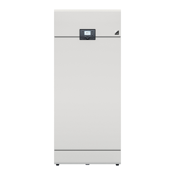
- Page 1 installation and maintenance manual FOR THE INSTALLER AND THE USER NESTA 300 kW FLOOR — STANDING CONDENSING BOILER...
-
Page 2: Table Of Contents
Package Contents ...........G-7 Strip and Electronic board....... I-48 .......G-8 roduct escrIPtIon Accessing the High Voltage Terminal Strip ..I-49 Nesta 300 ............G-8 Routing the Cables .......... I-49 General Description ..........G-8 Wiring Diagram ..........I-50 Frost Protection ............G-8 ........I-52 ommIssIonInG Safety Devices ............G-8... -
Page 3: About Our Boilers
Fig. 2. Gas Conversion Label - Typical ......G-7 Fig. 22. Routing the Electrical Cables ......I-49 Fig. 3. Nesta 300 Boiler Components - Front & Rear Fig. 23. Filling the System - Typical .........I-52 Views ................G-9 Fig. 24. Draining the Boiler - Typical ........I-56 Fig. -
Page 4: Liabilities Of The Manufacturer, The Installer And The End User
eneral nformatIon Liabilities of the Manufacturer, the Installer and the End user Manufacturer The installer shall provide the end-user with: Any relevant explanation about the op- î Our products are manufactured in compliance eration of the appliance and the heat- with the requirements of the applicable Europe- ing system as well as the safety devices an Directives and standards, and are therefore... -
Page 5: About This Manual
eneral nformatIon About this Manual This documentation is part of the product. It will be handed over to the end-user who will keep it, with all the other applicable documents, in a safe place and readily available for use. Before installing, operating or maintaining the appliance, please carefully read this manual and all the applicable documents provided with the components and accessories. -
Page 6: Safety Instructions
eneral nformatIon Safety Instructions IF YOU SMELL GAS: → DO NOT: → DO: Close the gas supply î Use an open fl ame î Open all doors and windows to î Smoke î ventilate the room î Use electrical devices (phones, î... -
Page 7: Boiler Marking
Boiler Marking Package Contents The data plate is located at the back of the boiler. The conversion sticker (yellow), is located under î A Nesta 300 boiler the appliance data plate. î An Installation and Maintenance manual Nesta Floor-Standing Condensing Boiler | Stojący kocioł kondensacyjny | Caldera de condensación de pie | Caldaia a condensazione Refer to “Unpacking the Product”... -
Page 8: General Description
Some optional equipment can be used with the These appliances are not provided with a built-in cir- Nesta boilers. Please contact your AIC Europe rep- culating pump. Therefore, the hydraulic system must resentative for more information and a list of availa- be equipped with at least one pump for standard sys- ble equipment. - Page 9 Fig. 3. Nesta 300 Boiler Components - Front & Rear Views Fan and burner assembly 16. Control panel with LCD display Air inlet duct 17. Burner plate temperature limit switch Ignition electrode 18. Air adapter Hoisting ring 19. Gas valve Water pressure sensor 20.
-
Page 10: Control Panel And Main Functions
roduct escriPtion Control Panel and Main Functions Fig. 4. Control Panel Chimney sweep function button - This button allows to Domestic Hot Water on/off button - Pressing this button ac- perform a measurement of the flue gas contents. tivates/deactivates of the Domestic Hot Water function ( Manual operation mode button - The operation de- LCD Display - The display illuminates whenever a control pends on the function defined for the relays (Expert Lev-... -
Page 11: Symbols And Messages On The Control Panel
roduct escriPtion Symbols and Messages on the Control The following symbols are displayed on the screen Panel (See Fig. 5): The following symbols are present on the control ). The time scale ( Comfort mode active ( panel (See Fig. 5): at the bottom of the display indicates the period during which this mode is active (in Domestic Hot Water mode. -
Page 12: Dimensions And Clearances
echnIcal PecIfIcatIons Dimensions and Clearances Dimensions & weight N 300 FS 1524 1324 1313 1098 dry weight G-12 A-136280_EN ● A... - Page 13 echnical pecificaTionS Connections N 300 FS supply/return connections ( ) Ø - [M] safety group connection ( ) Ø - [F] gas connection ( ) Ø - [M] flue gas exhaust connection Ø combustion air inlet connection Ø condensate drain connection Ø min.
-
Page 14: Performance And Efficiency Data
echnical pecificaTionS N 300 FS Performance and Efficiency Data (min. - max.)* G20/G25 31,0 - 280,0 heat input (net) 55,0 - 280,0 G20Y20** 31,0 - 280,0 G20/G25 30,0 - 272,0 heat output at 80/60°C 53,3 - 273,8 G20Y20** 30,0 - 272,0 G20/G25 33,2 - 300,0 heat output at 50/30°C... -
Page 15: Combustion Data
echnical pecificaTionS N 300 FS Combustion Data (min. - max.)* chimney type(s) B23, B23p, C43, C53, C63, C83 flue gas temperature at 80/60°C °C 55,7 - 61,9 flue gas temperature at 50/30°C °C 29,7 - 34,6 overheat flue gas temperature °C 97,0 min. - Page 16 echnical pecificaTionS N 300 FS Gas Data (min. - max.)* gas type(s) G20 - G20Y20 - G25 - G25.1 - G25.3 - G31 G20/G20Y20 (20 mbar) mbar 17 - 25 G25 (25 mbar) mbar 20 - 30 gas pressure G25.1 (25 mbar) mbar 18 - 33 G25.3 (25 mbar)
-
Page 17: Hydraulic Data
echnical pecificaTionS Hydraulic Data N 300 FS water content hydraulic pressure drop at ∆T = 20k mbar 30,31 minimum operating pressure maximum operating pressure maximum boiler supply temperature °C Pressure Drop Curve Flow rate [m3/h] Flow Rate N 300 FS minimum water flow rate at ∆T = 20k 11,22 G-17... -
Page 18: I Nstructions For The
nstructIons for the Safety Instructions for the User IF YOU SMELL GAS: → DO NOT: → DO: Close the gas supply î Use an open fl ame î Open all doors and windows to ven- î Smoke î tilate the room î... -
Page 19: U Ser
nstructIons for the Periodic checks If works need to be per- î formed close to the appli- ance (e.g. in the boiler room Check regularly that the wa- î or close to the air inlets), ter pressure of the system is make sure that the appli- at least 1.2 bar when cold. -
Page 20: Starting The Appliance
nstructIons for the Starting the Appliance Stopping the Appliance The first start-up of the boiler after its in- Conditions: stallation must be performed by a qual- None ified professional, according to the pro- cedure in “Start-up and Combustion Procedure: Adjustments” on page I-53. Push the On/Of switch located on the right side of the boiler. -
Page 21: What To Do If
nstructIons for the Cause Action What to Do if... 1. Check that the power button is in ON position (pushed in and illuminated). 2. Make sure the power supply is connected to the Boiler does not start No power supply mains. -
Page 22: Basic Settings
nstructIons for the Basic Settings Setting Procedure Controls/Screens Press the Heating mode selection button to toggle from one Heating mode mode to the other: selection • Automatic mode ( ) (to be programmed, refer to “Boiler Settings for the Installer” on page I-70. •... - Page 23 nstructIons for the Setting Procedure Controls/Screens Press the OK button (2) to access the end user menu. Times of start and end of Rotate the knob (1) to scroll through the menu until “Time Program heating circuit 1” (5) is highlighted. comfort mode schedule Press the OK button (2) to validate the selection...
- Page 24 nstructIons for the Setting Procedure Controls/Screens Press the OK button (2) to access the end-user menu. Language Selection Rotate the knob (1) to scroll through the menu until “Operator Section” (9) is highlighted. Press the OK button (2) to validate the selection Rotate the knob (1) to select the required language (EN, PL, CS, SK, SL, HU, EL, TR, TU, ES, IT, SR).
-
Page 25: Structure Of Menus For The End User
nstructIons for the Structure of Menus for the End User Some parameters are only visible if the heating circuit is installed Top menu Submenu 1 Submenu 2 Default Time of day and date Hours / Minutes 01:00 (hh:min) Ҙ (Adjust as required) Day / Month 01.01 (dd.mm) Ҙ... - Page 26 nstructIons for the Top menu Submenu 1 Submenu 2 Default Heating circuit 1 Room comfort setpoint 20°C Ҙ Room reduced setpoint 16°C Ҙ Room frost protection 10°C Ҙ setpoint Heating curve slope Ҙ Summer/winter heating limit 18°C Ҙ Flow temp setpoint room 65°C Ҙ...
-
Page 27: Safety Instructions For The Installation
roduct nstallatIon Safety Instructions for the Installation When the appliance is con- î nected to the electrical net- All connections (electrical, flue pipe, î work, it must be earthed. hydraulic, gas) must be carried out Make sure that a fuse or circuit breaker î... -
Page 28: Handling The Product
roduct nstallatIon Handling the Product Move the appliance carefully to its final po- sition. Make sure to comply with the recom- This appliance is heavy and î mended clearances (See “Dimensions and requires sufficient work- Clearances” on page G-12). force to move and handle it, If some height is required for condensate flow as well as an appropriate means of transport. -
Page 29: Removing And Installing The Access Panels
roduct nstallatIon Removing and Installing the Access Panels Top panel Conditions: Push the top panel downwards to engage Tools and Material: the studs into their receptacles. î Wrench, hex head, size 4 Side Panels Removal Procedure: Bottom: install six retained screws. Bottom Front Panel Top : Install four retained screws. -
Page 30: Requirements For The Hydraulic Connections
roduct nstallatIon Requirements for the Hydraulic Connec- tions Safety Instructions for the Primary Circuit Consult the appliance manufac- î turer to determine the compati- bility of the antifreeze product Make sure that the circuit is provided with with the appliance materials. a safety pressure relief valve and an ex- It is recommended to install the follow- î... -
Page 31: Water Quality Requirements To Prevent Scaling And Corrosion In A Heating System
roduct nstallatIon Water Quality Requirements to Prevent Scaling and Corrosion in a Heating System To prevent the formation of scale and sludge in a Additives can be used to keep the oxygen in î closed heating circuit through the penetration of ox- solution in the water. - Page 32 roduct nstallatIon Water Parameters Graph description: Above the curves, water treatment is In addition to the water hardness, other pa- Ÿ î required rameters of the water must be checked. Treat the water if the measured values are outside Below the curves, fi ll with untreated tap Ÿ...
-
Page 33: Typical Hydraulic Connections - Heating Circuit
roduct nstallatIon Typical Hydraulic Connections - Heating Circuit Isolating valve Filling valve Draining valve Check valve Expansion vessel Safety group (automatic air relief valve, manometer, safety valve), con- nected to the drain Circulating pump Removable fi lling hose Drain Fig. 10. Typical Heating System To make maintenance easier, we recommend to remove the plug from the drain connection and install an optional draining valve (see Fig. -
Page 34: Hydraulic Connections - Cascaded Boilers, With External Domestic Hot Water Tank And Plate Heat Exchanger
roduct nstallatIon Hydraulic Connections - Cascaded boilers, with External Domestic Hot Water Tank and Plate Heat Exchanger Isolating valve Heating circuit pump Filling valve DHW circuit pump Draining valve Check valve Motorised 3-way valve (when needed for low temp systems) Expansion vessel Heating circuit Safety group (automatic air relief valve, manome-... -
Page 35: Hydraulic Connections - Cascaded Boilers, With External Domestic Hot Water Tank And Low Loss Header
roduct nstallatIon Hydraulic Connections - Cascaded boilers, with External Domestic Hot Water Tank and Low Loss Header Isolating valve Heating circuit pump Filling valve DHW circuit pump Draining valve Check valve Motorised 3-way valve (when needed for low temp systems) Expansion vessel Heating circuit Safety group (automatic air relief valve, manome-... -
Page 36: Safety Instructions For The Chimney Connections
(at least 40 mm) between the spillage or appliance malfunc- appliance fl ue piping and combustible tion. Please contact your AIC materials, and between the fl ue pipe Technical Support for more in- and air inlet pipe if the latter is made of formation. - Page 37 roduct nstallatIon Plastic fl ue pipes should be î Flue pipe elements or PP air î allowed to expand under the inlet elements should not be eff ect of heat. Leave about screwed together. 10 mm between the pipe and the sleeve end stop.
-
Page 38: Chimney Connection
roduct nstallatIon Chimney Connection Description C (Closed) Appliance connected via its two ducts to a common duct system (part of the building) designed for more than one appliance. The common duct system consists of two ducts connected to a terminal, which at the same time admits fresh air to the burner and discharges the products of combustion to the outside through orifi ces that are either concentric or close enough to come under similar wind conditions. -
Page 39: Air Intake Grid Installation In Chimney Systems
Before installation, check on air in- î take grid sticker that it is the correct component for the boiler model. If not, contact your AIC representa- tive. 2. Install air intake grid into air inlet connection. 3. Secure with 2 screws. -
Page 40: Engineering The Chimney System
Make sure to install the boiler with the short- î est length of combustion air and flue ducts. When several boilers need to be connected î to a common duct, please contact your AIC representative for more information. I-40 A-136280_EN ● A... -
Page 41: Safety Instructions For The Gas Connection
Use a gas detection device or per- î form a bubble test to check for gas leaks. Never use an open fl ame, as Nesta 300 Gas valve it could result in an explosion. Gas pressure* Min - Max (mbar) -
Page 42: Gas Conversion
roduct nstallatIon Gas Conversion Connection of the boiler to a î different gas system should comply with local regulations and requirements. If the boiler was running before con- î Conversion of the appliance î version, allow it to cool down before from one gas type to another can performing any task. -
Page 43: Preparing The Boiler For Gas Conversion
Fig. 16. Gas Valve - Pre-adjustments for Propane Please be aware that conversion to a different gas type may require replacement for î a different mixer model. Please contact your AIC representative for more information. Boiler model Mixer model Insert... -
Page 44: Adjustment Of Fan Speeds
A password is required to access the speed for the gas type, boiler type and chim- Table 1 on page I-42. ney type. Refer to Engineer level. Please contact your AIC representative for more information. 18. Press OK ( ) to confirm and save the value. - Page 45 roduct nstallatIon Combustion Adjustment for Gas Conversion Conditions: î Press the Information button (2). The mod- ulation indicator (5) is displayed (in %). Tools and material: î Press the OK button (3), the indicator (5) î Flue gas analyser starts flashing. î...
- Page 46 roduct nstallatIon XXX% Fig. 19. Combustion Adjustment - Control Panel N 300 FS Combustion and Gas Values min. max. G20 (+/-0.3) G25 (+/-0.3) contents 10,5 10,5 G31 (+/-0.3) G20Y20 (+/-0.3) G20 (+/-0.3) G25 (+/-0.3) contents G31 (+/-0.3) G20Y20 (+/-0.3) 17 - 25 G20/G20Y20 (20 mbar) mbar G25 (25 mbar)
-
Page 47: Safety Instructions For The Electrical Connections
roduct nstallatIon Safety Instructions for the Electrical Connections Connections Any damaged power supply cable must be replaced using cables as described below and installed by a qualified professional. The cross-section of the wires should be Electrical connections must be carried = 2,5 mm , equipped with sleeves at L, out by a qualified professional in ac-... -
Page 48: Accessing The Low Voltage Terminal Strip And Electronic Board
roduct nstallatIon Accessing the Low Voltage Terminal Strip and Electronic board Conditions: Tools and material: î Wrench, hex head, size 4 Procedure: Remove center front panel, see “Removing and Installing the Access Panels” on page I-29. Remove one screw ( ) at the bottom of the electronic bay access panel. -
Page 49: Accessing The High Voltage Terminal Strip
roduct nstallatIon Accessing the High Voltage Terminal Strip Routing the Cables Make sure that the power supply to the appliance is deactivated (power supply cable disconnected from the boiler) before accessing the high voltage terminal strip. Route Conditions: voltage cables Route high through these... -
Page 50: Wiring Diagram
roduct nstallatIon Wiring Diagram Door Temp Condensate Limit Level Switch Gas Valve GNYE Gas pressure Flue Gas Switch Temperature Sensor GNYE GNYE Ignition Ignition Transformer Grounding Strip Electrode High Voltage Cable GNYE GNYE Safety Water Temperature Switch 8 9 10 11 12 1 2 3 4 5 6 7 8 1 2 3 4 N L N L... - Page 51 roduct nstallatIon Front Panel 1 ty Water Pressure Sensor Signal Optional Inlet Temperature Sensor LMS-14 LMS-14 LMS-14 Outlet Temperature Sensor Optional GNYE DC24V GNYE Max 625mA WEB Server Optional +24V Ethernet 2 3 4 HALL RJ45 QAA74 GNYE Optional QAA55 2 options Front Panel 2 Alternative...
-
Page 52: Ommissioning
ommIssIonIng Safety Instructions Before Start-up Filling the System Conditions: Procedure: Check that all connections (electrical, î 1. Connect the fi lling hose ( ) to the system fl ue pipe, hydraulic, gas) have been fi lling valve ( ) and to the water network tap. carried out and that they are tight and secure. -
Page 53: Start-Up And Combustion Adjustments
ommissioning Start-up and Combustion Adjustments Check CO contents in the flue gas at max Conditions: output as follows: Tools and material: î Press the Information button ( ). The mod- ulation indicator is displayed (in %). î Flue gas analyser î... -
Page 54: M Aintenance
aIntenance Safety Instructions for Maintenance The maintenance of the ap- î pliance and its components must be carried out by a qualifi ed professional. Inspection and maintenance tasks î Defective parts and components may î must be carried out by a qualifi ed and only be replaced by genuine factory certifi ed professional, at least once a parts or parts approved by the manu-... -
Page 55: Maintenance Requirements
aintenance Maintenance Requirements @ inspection @ maintenance Tasks (1 year) (2 years max) Check that the boiler room ventilation / boiler air and flue ducts are unobstructed. Verify flue gas and combustion air ducts are in good condi- tion, sealed tight and properly supported. Open the front panel and check the general condition inside the cabinet. -
Page 56: Shutting Down For Maintenance
aintenance Shutting Down for Maintenance Restarting after Maintenance Conditions: Conditions: None Procedure: Procedure: Push in the On/Of switch located on the right side of the boiler. Push the On/Of switch located on the right side of the boiler. When in the On position, the switch re- mains pushed in and is illuminated. -
Page 57: Cleaning The Condensate Pipe And Trap
aintenance Cleaning the Condensate Pipe and Trap Remove the cover gasket ( ). Discard. Wipe clean the condensate level switch ( Conditions: attached to the cover. Remove and replace as required. Clean the deposits in the condensate trap ( Tools and material: using clear water and a cloth. -
Page 58: Removing And Installing The Fan And Air Adapter Assembly
aintenance Removing and Installing the Fan and Air Adapter Assembly Conditions: Remove the burner, as required, refer to “Removing and Installing the Burner” on page I-63. Tools and material: Clean the combustion chamber, as required, î Wrench, hex head, sizes 4 and 6 refer to “Checking and Cleaning the Com- î... - Page 59 aintenance Fig. 26. Removing and Installing the Fan and Adapter Assembly I-59 A-136280_EN ● A...
-
Page 60: Removing And Installing The Air-Gas Mixer
aintenance Removing and Installing the Air-Gas Mixer Conditions: î Fan and Air Adapter Assembly removed, see Installation Procedure “Removing and Installing the Fan and Air Some hardware require the use of Loctite Adapter Assembly” on page I-58. thread sealant 577 at installation. When this is the case, a “drop”... - Page 61 aintenance Fig. 27. Removing and Installing the Air-gas Mixer I-61 A-136280_EN ● A...
-
Page 62: Removing And Installing The Ignition And Ionization Electrodes
aintenance Removing and Installing the Ignition and Release two screws ( ) from the electrode Ionization Electrodes flange. Remove the electrode and screws from the burner plate ( ). Discard, as required. Conditions: Remove electrode gasket ( ) and discard, as Tools and material: required. -
Page 63: Removing And Installing The Burner
aintenance Removing and Installing the Burner To ensure correct tightness of î Conditions: the combustion chamber, it is essential to replace the old gas- î Fan and air adapter assembly removed, refer kets with new ones, clean the to “Removing and Installing the Fan and Air contact surfaces and install the Adapter Assembly”... -
Page 64: Checking And Cleaning The Combustion Chamber
aintenance Checking and Cleaning the Combustion Replacing the Gas Valve Filter Chamber Conditions: Conditions: î Left side top panel removed, refer to “Removing and Installing the Access Panels” on page I-29. î Burner removed, see “Removing and Install- ing the Burner” on page I-63. Cleaning Procedure (Fig. -
Page 65: Checking The Flue Gas (Fps) And Air (Aps) Pressure Switches Operation
aintenance Checking the Flue Gas (FPS) and Air (APS) FPS: blow air into the hose while it is con- nected to the flue pressure switch and to the Pressure Switches operation measuring device. APS: suck air from the hose while it is con- Conditions: nected to the air pressure switch and to the measuring device. -
Page 66: Optional Modules
ddItIonal nformatIon for the nstaller Optional Modules Extension Modules & Cable Hub Web Server Module Nesta boilers can control 3 heating circuits with Through the use of this module, you can connect mixing functions, using 3 extension modules. Each to an Ethernet and get remote access to the boiler extension supply needs to be provided with power and all the heating system via the Internet. -
Page 67: Boilers In A Cascade System
dditionAl nformAtion for the nstAller Boilers in a Cascade System The principal boiler activates the required functions In a heating system comprised of several boilers, it and shows the additional menus with the parame- is important that the power generated by the boilers ters for use with the cascaded system. - Page 68 dditionAl nformAtion for the nstAller I-68 A-136280_EN ● A...
- Page 69 dditionAl nformAtion for the nstAller I-69 A-136280_EN ● A...
-
Page 70: Boiler Settings For The Installer
U-25. The menus for the qualified professional (Commissioning and Engineer) are described in the following pages. A password is required to access the Engineer level. Please contact your AIC Menus and Settings representative for more information. To access the Commissioning and the Engineer... - Page 71 dditionAl nformAtion for the nstAller Top menu Level Pgm No. Submenu 1 Submenu 2 Default Setting Direct Adjustment Automatic storage Ҙ Storage Ÿ Storage with confirma- with con- Ÿ firmation tion Units °C, bar Ҙ Ÿ °C, bar °F, PSI Ÿ...
- Page 72 dditionAl nformAtion for the nstAller Top menu Level Pgm No. Submenu 1 Submenu 2 Default Setting Room comfort setpoint Heating Ҙ 20.0°C circuit 1 Room reduced setpoint Ҙ 16.0°C Room frost protection Ҙ 10.0°C setpoint Comfort setpoint max Ҙ 35.0°C Heating curve slope Ҙ...
- Page 73 dditionAl nformAtion for the nstAller Top menu Level Submenu 1 Submenu 2 Default Setting Pgm No. Excess heat draw Heating cir- Ҙ Ÿ Heating mode Always cuit 1 (Cnt’d) Ÿ Always Ÿ With bufer Ҙ Ÿ Ÿ With prim contr/system Ҙ...
-
Page 74: Error Codes And Solutions
Check connection and/or sensor. Re- Outside temperature sen- place as required. sor error Emergency operation Contact AIC technical support. Boiler temperature 1, Short circuit or Open circuit Check connection and sensor. Re- sensor error boiler fl ow sensor. place as required. - Page 75 BSB RF communication Check bus connection and compo- error nents. Internal fault in controller, pro- Data overrun in EEPROM Contact AIC technical support. cess sensor Extension module 1, error Check extension module connections. Extension module 2, error Check extension module connections.
- Page 76 Check connection and component Lack of gas, Reset, if the fault re-occurs more than 3 times, contact AIC technical support. Safety time for establish- ment of fl ame exceeded Check ignition electrode and ionization Polarity of mains connection,...
- Page 77 Allow the circuit to cool down and carry Temperature limiter heating out reset; if the fault occurs several circuit 1 times inform AIC technical suport. Allow the circuit to cool down and carry Temperature limiter heating out reset; if the fault occurs several circuit 2 times inform AIC technical suport.
- Page 78 dditionAl nformAtion for the nstAller Error Fault description Explanation Action(s) code Temperature dif erence, Check the heating system external hy- heat exchanger too large draulic components. Mains frequency outside Check correct electric supply in boiler permissible range terminals. DHW charging tempera- Check connection and sensor.
-
Page 79: Maintenance Messages
3 times inform AIC technical suport. Internal repetition Contact AIC technical support Repetition speed Contact AIC technical support Shut of gas supply and contact AIC Extraneous light technical support Mains undervoltage Check electric supply in boiler terminals Fan speed tolerance Check air supply Check connection and sensor. -
Page 80: Troubleshooting
dditionAl nformAtion for the nstAller Troubleshooting Problem Cause(s) Solution(s) 1. Check that the power button is in ON position (pushed in and illuminated) 2. Make sure the power supply cable is Boiler does not start No power supply connected to the mains 3. - Page 81 dditionAl nformAtion for the nstAller Problem Cause(s) Solution(s) Gas valve malfunction Burner does not start after receiving Fan malfunction Check wiring connections Check components signal from boiler controller Ignition/ionization electrode mal- function Check the values with a gas analyser and Combustion chamber gets dirty Wrong combustion settings readjust as required.
-
Page 82: Installation Checklist
dditionAl nformAtion for the nstAller Installation Checklist Unit Values/Comments General/heating system Type of building/system Commercial purpose (Y/N) ? Year of manufacture Output of system Heated surface m² Number of heating circuits: • Floor heating • Radiators • Other Cascade (Y/N)? Number of appliances? Water Water hardness at start up... - Page 83 dditionAl nformAtion for the nstAller Unit Values/Comments Plate heat exchanger in the system (Y/N)? Type? Low loss header in system (Y/N)? Type ? Number of mixers ? Buf er tank (Y/N)? Size? DHW tank (Y/N)? Type? Pump(s) (Y/N)? Type? • In which circuit(s) •...
- Page 84 dditionAl nformAtion for the nstAller Unit Values/Comments Controller Appliance controller? Other controller (Y/N)? Type? Optional modules installed (Y/N) • Type? Optional items installed (Y/N)? • Outdoor sensor (Y/N)? Type? • Room unit(s) (Y/N)? Type? • Others? Miscellaneous The end user has received all rele- vant information (Y/N)? The end user has received all rele- vant documents (Y/N)?
-
Page 85: Combustion Parameters - Log Sheet
dditionAl nformAtion for the nstAller Combustion Parameters - Log Sheet Date & Flue gas T° Remarks Name Signature I-85 A-136280_EN ● A... -
Page 86: Water Parameters - Log Sheet
dditionAl nformAtion for the nstAller Water Parameters - Log Sheet Recommended parameters to be checked during installation and operation of the boiler: Meter reading before initial filling: Z=…………… m Date Meter Quantity of Total alkaline Conductivity System Addition Signature reading Water earths or total value... -
Page 87: Gas Conversion - Log Sheet
dditionAl nformAtion for the nstAller Gas conversion - Log Sheet This appliance was converted on ____/____/_20_____ (dd/mm/yyyy) from gas __________________ to gas __________________ (Gas Type: Natural gas G20/G20Y20, G25, G25.3/ Propane G31) with Kit _________________________________________________ (fill in with kit name or number (if required) or cross it out) by: ______________________________________________________ (name and address of organization making this conversion, who accepts responsibility for the correctness of this conversion) This appliance was converted on ____/____/_20_____... -
Page 88: D Eclaration Of C Onformity
eclaratIon of onformIty I-88 A-136280_EN ● A... - Page 89 NOTES I-89 A-136280_EN ● A...
- Page 90 NOTES I-90 A-136280_EN ● A...
- Page 91 NOTES I-91 A-136280_EN ● A...
- Page 92 AIC Europe B.V. Graafschap Hornelaan 163A NL-6001 AC Weert The Netherlands www.myaic.eu...
Need help?
Do you have a question about the NESTA 300 and is the answer not in the manual?
Questions and answers