Advertisement
Quick Links
DirectCommand
Apache AS715/1010/1210 (MY 2009-2010)
Note: Indented items indicate parts included in
an assembly listed above
Part Name/Description
DirectCommand Kit
Generic Cable Installation Kit
Hardware Kit – Large Module
Installation Instructions
CAN Bus Y-Splice
CAN Bus Terminator
Liquid Product Control Module
CAN Bus Stub – 8 in.
Flow Control Cable
Implement Stub
Apache Switchbox Adapter
10 Section Boom Cable
Hi-Current Power/CAN Bus Extension
Power Cable
Auxiliary Input Module Kit
Deutsch Dust Plug – 6-pin
CAN Y-Splice
CAN Bus Stub – 1 ft.
Auxiliary Input Module
RAM Rail Mount Kit
RAM 201UD – 5" Arm
RAM 2461U – Base
RAM 235U – Base, Double U-Bolt
PN: 2005943 Rev. D
Installation
Part Number
4100589
2000901-1
2001354-1
2005943
4000137
4000141
4000394
4000450-1
4000451-6
4000495-1
4001615
4001792-6
4001808-24
4002016-5
4100506
2002899-6
4000137
4000219-1
4000437
4100101
4000279
4000280
4000281
December 2013
Ag Leader Technology
Quantity
1
1
1
1
1
1
1
1
1
1
1
1
1
1
1
1
1
1
1
1
1
1
1
Page 1 of 13
Advertisement

Related Manuals for Ag Leader Technology DirectCommand


Summary of Contents for Ag Leader Technology DirectCommand
- Page 1 DirectCommand Ag Leader Technology Installation Apache AS715/1010/1210 (MY 2009-2010) Note: Indented items indicate parts included in an assembly listed above Part Name/Description Part Number Quantity DirectCommand Kit 4100589 Generic Cable Installation Kit 2000901-1 Hardware Kit – Large Module 2001354-1 Installation Instructions...
-
Page 2: Table Of Contents
Important by closely following these step-by-step instructions. If you have Notices questions, call Ag Leader Technology at 515-232-5363 x 1. Direction words (LEFT and RIGHT) are commonly used when describing an installation procedure. Interpret direction words as if standing behind equipment and looking forward. -
Page 3: Common Components
Ag Leader Technology Installation Apache AS715/1010/1210 (MY 2009-2010) This section contains illustrations of components common to all Common DirectCommand installations. Their purpose is to ensure proper Components identification and installation in the sections that follow. Blue Seal Brown Seal CAN Bus connectors 1. -
Page 4: Component And Cable Layout
Ag Leader Technology DirectCommand Installation Apache AS715/1010/1210 (MY 2009-2010) Component and Cable Layout PN: 2005943 Rev. D Page 4 of 13 December 2013... -
Page 5: Safety Notices
IMPORTANT: Check behind vehicle and implement panels for any hoses, wiring, controls, etc. that could be damaged when drilling any mounting holes. IMPORTANT: Disconnect the Display, DirectCommand components and flow meter from electrical system when welding on equipment or jump starting unit to prevent component damage... -
Page 6: Installing The Display
Ag Leader Technology DirectCommand Installation Apache AS715/1010/1210 (MY 2009-2010) Parts required for procedure: Installing • (1) Ag Leader INTEGRA Display PN: 4002000 the Display • (1) EDGE Display PN: 4001500 • (1) Insight Display PN: 4001000 From RAM Mount Kit: •... -
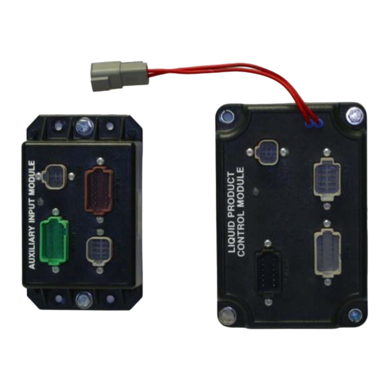
Page 7: Installing The Cab Cabling And Auxiliary Input Module
DirectCommand Ag Leader Technology Installation Apache AS715/1010/1210 (MY 2009-2010) Display Mounting Rail Mount the Display in a convenient place for operation, but out of the operator’s line of sight while operating the sprayer. Parts required for procedure: Installing From Direct Command Kit: the Cab •... - Page 8 Ag Leader Technology DirectCommand Installation Apache AS715/1010/1210 (MY 2009-2010) Route the opposite end of the Display Cable towards the Auxiliary Input Module. Connect the Power Control Relay, PN: 4000708-1, to the Display Cable at the black 4-pin Weatherpack Connector. Connect the single end of the CAN Y-Splice, PN: 4000137, from the Auxiliary Input Module Kit to the mating connector on the Display Cable.
- Page 9 DirectCommand Ag Leader Technology Installation Apache AS715/1010/1210 (MY 2009-2010) “AUXILIARY INPUT MODULE” into the Auxiliary Input Module receptacle labeled SWITCH B. 11. Connect the brown plug labeled “APACHE” on the Switchbox Adapter Cable into the machine harness. 12. Use the Deutsch 6-Pin Dust Plug, PN: 2002899-6, to fill the empty receptacle labeled RADAR on the Auxiliary Input Module.
-
Page 10: Installing The External Cabling And Liquid Control Module
Ag Leader Technology DirectCommand Installation Apache AS715/1010/1210 (MY 2009-2010) Parts required for procedure: Installing From Direct Command Kit: the External • (1) Hardware Kit – Large Module PN: 2001354-1 Cabling and • (1) CAN Y-Splice PN: 4000137 • (1) CAN Bus Terminator... - Page 11 Control Module. 8. Connect the single end of the CAN Y-Splice from the DirectCommand Kit into the mating connector on the Hi-Current Power/CAN Bus Extension Cable. 9. Plug the black 4 pin connector of the CAN Bus Stub – 8 in. into the gray side of the Y-Splice.
- Page 12 Ag Leader Technology DirectCommand Installation Apache AS715/1010/1210 (MY 2009-2010) 12. Plug the gray 12-pin plug on the 10 Section Boom Cable into the receptacle labeled BOOM on the Liquid Control Module. 13. Route the opposite end of the 10 Section Boom Cable to the sprayer boom valves.
-
Page 13: Setting Up The Display
DirectCommand Ag Leader Technology Installation Apache AS715/1010/1210 (MY 2009-2010) 1. Refer to the Quick Reference Guide, PN: 2002831-38 for Setting up setting up the Display the Display 2. Enter the default settings from the following chart as an initial setup.
Need help?
Do you have a question about the DirectCommand and is the answer not in the manual?
Questions and answers