Table of Contents
Advertisement
Quick Links
Advertisement
Table of Contents
Troubleshooting

Related Manuals for Ag Leader Technology EDGE


Summary of Contents for Ag Leader Technology EDGE
- Page 1 EDGE U ANUAL IRMWARE ERSION PN: 4001662 Rev.A...
- Page 2 PN: 4001662 Rev.A...
-
Page 3: Table Of Contents
Cross-References and Web Links ..............6 Viewing this Manual Online ................7 How to Find Information You’re Looking For ............7 Display Hardware..................8 EDGE Installation Instructions ...............9 Mounting the EDGE Display ..............9 EDGE Fuse Installation and Replacement..........10 EDGE Screen Icon Conventions ..............11 Setup................13 System Functionality ..................13 Home Screen....................14... - Page 4 EDGE User Manual Edit Legend.....................34 Create a Boundary....................35 Start Boundary ...................35 Pause Boundary..................36 View Boundary....................36 View Map Markers..................37 Summary ......................38 Select Summary ................38 Diagnostics......................39 Device Information..................39 Memory .....................40 Display ......................40 GPS ..................45 GPS General Tab....................45 OmniSTAR Settings..................47 Serial Port Settings ..................48 GPS Diagnostics ....................50...
- Page 5 EDGE Firmware Version 1.5 Planting Setup Tabs ..................71 Create a Planting Configuration .................72 Configuration Settings ..................73 Configuration Settings: Equipment Configuration ...........74 Equipment Configuration Settings - SeedCommand ....74 Speed Input Settings ..................75 Calibrate Distance................75 Auxilliary Input Settings (Switch Mapping) ............76 Add Auxiliary Input Settings ...........
- Page 6 EDGE User Manual Checking AutoSwath Performance for Clutch Control........109 If Gaps Appear on the On-Screen Map ..........110 Hydraulic Seed Rate Control ................111 Hydraulic Seed Rate Control Configuration ..........112 Controller Settings for Hydraulic Seed Rate Motor Drives ......113 Channel Tabs .................113 Control Valve Settings - PWM..........
- Page 7 EDGE Firmware Version 1.5 Configuration Settings - DirectCommand........144 Speed Input Settings ................145 Calibrate Distance................145 Auxiliary Input Settings ................146 Add Auxiliary Input Settings ........... 147 AutoSwath ....................148 AutoSwath Notes ................149 Vehicle Tab ....................150 GPS Offsets .....................151 Antenna Tab...................152 Mount Tab..................153 Hitch Tab..................153...
- Page 8 EDGE User Manual Run Time Environment: Rate Screen..............191 Target Rate ..................191 Rate Screen: Container Level ..............192 Tank Fill ..................192 Tank Empty ..................192 Tank Partial Fill ................193 Adjust Container Amount............193 Tank Alarms ...................194 Container Alarm Screen............194 Rate Screen: Liquid Flow/Pressure .............195 Rate Screen: Spinner SpreaderSettings............196...
- Page 9 EDGE Firmware Version 1.5 Harvest Button on Task Bar..............235 Map Screen: Flow Delay ................235 Run Time Environment: Harvest Screen ............236 Harvest Screen Display Items..............237 Harvest Screen - Active Display Items............238 Harvest Setup Tabs ..................239 Create a Harvest Configuration ................240 Configuration Settings................241 Primary and Backup Speed Source ...........241...
- Page 10 EDGE User Manual PN: 4001662 Rev.A...
-
Page 11: General Content
Introduction and Company Profile ABOUT US Welcome to the Ag Leader Technology family. Ag Leader Technology, Inc. is the global leader in yield monitor and precision farming systems and is committed to meeting the present and future needs of the agriculture industry by providing high quality products and first class customer support. - Page 12 EDGE display a great investment for any operation looking for an easy-to-use, input-cost saving solution. The EDGE display has its own internal memory for recording GPS and logging all information collected during various field activities. No external data card is needed for in-field data collection.
- Page 13 EDGE Firmware Version 1.5 SERVICE There are no user-serviceable parts inside the EDGE display. Contact Ag Leader Technical Support for a Return Material Authorization (RMA). ph: (515) 232-5363 fax: (515) 232-3595 e-mail: support@agleader.com Note: This display has an internal lithium coin cell battery and an internal nickel metal hydride battery.
- Page 14 EDGE User Manual DATA CARD USAGE The EDGE uses a compact flash card for transferring data in and out of the display. The system is compatible with all current card sizes; 64 MB is the minimum recommended size for use with the system.
- Page 15 SYSTEM UPGRADES Ag Leader Technology will periodically provide operating program updates that will improve the performance of your EDGE System. Required software updates will be available free of charge for download from . On occasion, major releases will be made available www.agleader.com...
-
Page 16: Conventions Used In This Manual
Links to web sites are shown in blue, italicized, and underlined text, as in the following example: To see the Ag Leader Technology Web site, go to this Web link: www.agleader.com... -
Page 17: Viewing This Manual Online
Ag Leader Web site, and click the Support link. You should see a page titled “Manuals and Quick Reference Sheets.” To view and/or print the EDGE User Manual online, you will need the Adobe Acrobat or Adobe Reader .pdf file format. The Adobe Reader software comes pre-installed on most personal computers. -
Page 18: Display Hardware
The built-in speaker is used for audible warnings. The speaker volume can be adjusted through the console setup routine. 5 Power/Reset The Power/Reset switch is used for turning the EDGE display on and off in installations where the system is connected to a continuous power supply. If Switch the EDGE display ever stops responding, the manual power switch may be held in for five seconds to restart the system. -
Page 19: Edge Installation Instructions
• The display must not interfere with or limit access to any of the existing machine controls. • The EDGE CAN system cabling be routed and secured without interfering with existing machine controls. If drilling holes is required during the mounting... -
Page 20: Edge Fuse Installation And Replacement
EDGE User Manual EDGE Fuse Installation and Replacement Note: The fuse is to be placed in the fuseholder in-line with the battery power cable and used with display only. PN: 4001662 Rev.A... -
Page 21: Edge Screen Icon Conventions
EDGE Firmware Version 1.5 EDGE Screen Icon Conventions The following control buttons are made available for entering names and calibration values into the EDGE system. Function Button Data Entry Screen An on-screen Keyboard is made available when appropriate for use during all setup processes. - Page 22 EDGE User Manual PN: 4001662 Rev.A...
-
Page 23: Setup
Setup System Functionality Prior to setup, most of the functionality of the EDGE system is not available until the basic setup process is completed, and the Home screen will look like the picture below. The Run Time Environment is not accessible, because the Map button does not appear on the task bar at bottom. -
Page 24: Home Screen
EDGE User Manual Home Screen After a Grower, Farm and Field has been selected, the Home screen will appear as shown below. Specific functions available at the Home screen are described in the table below. Button Description The Diagnostics button opens screens that display Device Information, Memory, Display, and module diagnostics. -
Page 25: Setup Screen
EDGE Firmware Version 1.5 Setup Screen The Setup Screen is where you can access management information, adjust console and GPS settings, and specify field operations. Begin by going to the Home Screen, and pressing the Setup (wrench) tool. The Setup Screen appears, as shown below. -
Page 26: Management
EDGE User Manual Management The Management tabs, which are accessible from the Management button on the Setup screen, include Grower, Season and Field. • For information on the Season Tab, See “Season Management Tab” on page 18. • For information on the Field Tab, See “Field Management Tab”... -
Page 27: Importing An .Msf File
EDGE Firmware Version 1.5 Importing an .MSF File A Management Setup File (.msf) is a file format that allows the EDGE display to import Grower and Field information from desktop software via a Compact Flash Card. Follow the process outlined below to import desktop software information from your Compact Flash Card. -
Page 28: Season Management Tab
EDGE User Manual Importing an msf File - continued 3 Open this folder by pressing the Plus sign to the left of the folder. Highlight the desired .msf file and press the checkmark box. 4 The .msf file now appears under the Grower Tab on the Grower list. -
Page 29: Field Management Tab
EDGE Firmware Version 1.5 Field Management Tab A field consists of one or more outer boundaries. Each outer boundary can contain one or more inner boundaries used to define any combination of roadways, waterways, building sites, or bodies of water. If the display will... -
Page 30: Field Management Tab - Continued
EDGE User Manual Field Management Tab - continued • Press the Wrench Button to add or edit information regarding that field and its boundary. The Field Information screen opens, showing the name of that field in the Title Bar. The example below shows the “160”... -
Page 31: Import And Export Boundaries
EDGE Firmware Version 1.5 Import and Export Boundaries Boundaries can be created with the EDGE display or imported from desktop GIS software. For more information on creating boundaries, see . Any boundary files present in the EDGE “Create a Boundary” on page 35 display can also be exported for use in desktop mapping software. -
Page 32: Boundary Export
EDGE User Manual Boundary Export 1 To export a boundary to the external data card, press Export. 2 A screen appears, telling you that the boundary was exported successfully. Press the checkmark box. 3 Press the checkmark box on the View Boundary screen. -
Page 33: Console
To make these changes effective, press the checkmark/ Shutdown button. Note: The EDGE display will then shut down immediately. If you do not want to shut the monitor down, press the Close (Red X) button. -
Page 34: Memory Tab
• Restore Backup. Press to restore a backup file from the external data card to the internal memory of the EDGE monitor. • Copy to Card. Copies files which have not yet been copied to the external storage card. (Log files are stored using the .ilf file format). -
Page 35: Features Tab
Features Tab Unlock codes are unique to the serial number of each EDGE display and the feature registration number. You must supply these numbers to your Ag Leader dealer when purchasing any unlock codes. Press the Unlock button, and the Feature Registration box appears. -
Page 36: Advanced Tab
EDGE users: • Copy Log Files to Memory Card at Shutdown - Checking this checkbox will copy all log files to the external memory card when the EDGE display is turned off. • Copy All Log Files. Press to copy all logged data in the display to the external storage card. -
Page 37: Field Notes
EDGE Firmware Version 1.5 Field Notes Markers are a collection of point objects shown as icons on the Map Screen. As the name suggests, markers allow the operator to mark mapping points “on the go” and thus identify specific features within a field. -
Page 38: Start Field Operation
EDGE User Manual Field Notes (continued) For information on viewing the Field Notes on the Map Screen, See “View Map Markers” on page 37. Start Field Operation You can start field operations after setting up a Grower, Farm and Field;... - Page 39 EDGE Firmware Version 1.5 Start Field Operation (continued) 1 First, enter a Growing Season and Grower either by using the drop- down arrows to select existing ones, or by pressing on the Add (plus sign) arrow to create new ones. Press the blue right-arrow key at the bottom of the screen to proceed to the next step.
-
Page 40: Run Time Environment: Map Screen
EDGE User Manual Run Time Environment: Map Screen The appearance of the map screen varies, depending upon which operation you are performing. As examples, typical map screens for Tillage and Harvest are shown below. Data shown at the Title Bar at the top of the Map Screen show speed and distance logged. -
Page 41: Task Bar Buttons
EDGE Firmware Version 1.5 Task Bar Buttons The task bar displays buttons relating to various functions of the EDGE monitor. These buttons include Home, Mapping, Liquid Rate Control, Planting Rate Control, Harvest, Autoswath, and Logging. These buttons are shown in front of a green background when you are at that screen;... -
Page 42: Map Screen Icons
EDGE User Manual Map Screen Icons Icon Description The GPS button in the upper left-hand corner of the Map screen, displays the following colors: • Green if you are receiving a differential GPS signal • Yellow if you are receiving GPS, but no differential signal •... -
Page 43: Map Screen Status Items
EDGE Firmware Version 1.5 Map Screen Icons - continued Icon Description Press the center of the Map Screen, and four arrow icons appears around the vehicle icon. An example of one of these arrow buttons is shown at left. Pressing these arrow icons will move the center of the Map Screen in the direction of the arrow button. -
Page 44: Edit Legend
EDGE User Manual Edit Legend By pressing on the Legend, the Legend Settings screen appears, as shown below. The Legend Settings screen allows you to change the default legend for the rate applied. Note: Legend settings changes that are made at this screen will affect all regions. -
Page 45: Create A Boundary
Start Boundary 1 You can create two types of Map Screen boundaries in the EDGE display: Outer boundaries delineate the borders of an entire field; inner boundaries mark specific features within that field, such as waterways or buildings. -
Page 46: Pause Boundary
EDGE User Manual Start Boundary (continued) 2 If you are creating an Inner Boundary, choose either Roadway, Body of Water, Waterway, Buildings or Undefined. 3 The Boundary Offset feature enables mapping a boundary at a user- defined distance to the left or right of the GPS antenna centerline. -
Page 47: View Map Markers
EDGE Firmware Version 1.5 View Map Markers Pressing on the View Map Markers button on the Create Boundary screen cycles this screen to the Map Markers screen, as shown below. The Map Markers screen shows all of the Markers that you created in “Field Notes”... -
Page 48: Summary
EDGE User Manual Summary Press the Summary button at the bottom of the Home Screen to view a summary information, which shows you field totals and averages for a specific field. If you have performed only one instance in a specific field, the Summary Screen appears, as shown below. -
Page 49: Diagnostics
EDGE Firmware Version 1.5 Diagnostics Pressing on the Diagnostics button on the Home Screen summons the Diagnostics screens that pertain to your configuration. Technical support may request that you look at these screens for help in diagnosing a problem. Three screens that appear for all configurations include Device Information, Memory and Display, which are described in the following section. -
Page 50: Memory
The Memory screen shows information about memory usage, both for the display as well as an external memory card. Display The Display screen shows generalized diagnostic information about the EDGE display, including display temperature, as well as display and CAN Bus voltage. PN: 4001662 Rev.A... - Page 51 EDGE Firmware Version 1.5 Setup - Index calibrate touchscreen 23 CAN device list 39 change icon 27 add field 19 clear bounds add field note 27 field tab add grower 16 clear bounds 20 advanced parameters 26 clear internal memory 25...
- Page 52 EDGE User Manual device information 39 field operation wizard 28 CAN device list 39 operating configuration selection 29 diagnostics 39 field tab 19 CAN device list 39 area 20 device information 39 boundary 20 display 40 farm 20 firmware ID 39...
- Page 53 EDGE Firmware Version 1.5 start field operation button 14 view operation summary button 14 management button 15 wrench button 14 management tabs 16 map button 31 map options icon 32 map screen 30 icon selection 27 arrow icons 33 ilf file format 24...
- Page 54 EDGE User Manual legend settings time zone 23 reset legend 34 title bar 30 restore backup 24 revision 39 run time units diagnostics Imperial 24 run time 39 metric 24 run time environment unlock button 25 map screen 30 upgrade...
-
Page 55: Gps
During your field operation, the GPS button in the upper left-hand side of the Map Screen should appear as green, which means you are receiving a differential GPS signal. If this icon appears yellow, you are still receiving GPS but are not receiving a differential signal; and if it appears gray then you have lost GPS. - Page 56 EDGE User Manual GPS General Tab (continued) • Age of Differential - Displays the elapsed time since reception of last differential correction signal. The Age of Differential button is only functional when GPS is connnected. • Port Settings - Displays the Serial Port Settings screen, where you can adjust GPS output.
-
Page 57: Omnistar Settings
EDGE Firmware Version 1.5 OmniSTAR Settings Pressing the Wrench Button on the GPS General Tab opens the OmniSTAR Settings screen, as shown below, where you can view differential source and frequency settings. Note: The use of OmniSTAR® differential requires purchase of a subscription from OmniSTAR. -
Page 58: Serial Port Settings
EDGE User Manual Serial Port Settings A Serial Port Settings screen, where you can adjust GPS output, is shown for both Port A and Port B. To go to this screen, first go to the Home screen, press the Wrench Button and go to the Setup Screen. Press the GPS button, and at the GPS General Tab appears, press the Port Settings button. - Page 59 Serial Port Settings (continued) • Output Rate (Hz) - Represents the cyclical rate (in Hz) at which the receiver sends information to the EDGE display. This field shows a value of either 1 or ASAP. - The default rate is 1 Hz.
-
Page 60: Gps Diagnostics
EDGE User Manual GPS Diagnostics To access Diagnostic information about the GPS signal, press the Satellite icon that appears in the top-left corner of the Map Screen. GPS Information then appears on three different GPS Information screens. You can cycle through these screens by pressing the blue right-arrow button. -
Page 61: Gps Information - Second Screen
EDGE Firmware Version 1.5 GPS Information - Second Screen • UTC Time - UTC is an acronym for Coordinated Universal Time, a high- precision atomic time standard that defines local time throughout the world. Different versions of universal time use atomic clocks to correct for irregularities in the Earth's rotation and orbit. - Page 62 EDGE User Manual GPS Information - Second Screen (continued) • SNR - If your receiver is using Beacon differential corrections, the frequency and signal to noise ratio (SNR) will be displayed. Signal-to- Noise Ratio (SNR) indicates the strength of the differential correction signal in relation to the amount of background noise that can interfere with signal reception.
-
Page 63: Gps Information - Third Screen
EDGE Firmware Version 1.5 GPS Information - Third Screen Note: The settings shown on this GPS Information screen varies, depending upon your model of GPS receiver. • Receiver ID, Firmware Version, Serial Number, Receiver Voltage. • Fast Update Rate - The Fast Update Rate indicates whether your receiver is capable of outputting an update rate faster than 1 Hz per second. - Page 64 EDGE User Manual PN: 4001662 Rev.A...
- Page 65 EDGE Firmware Version 1.5 Index - GPS GGA 49 GLL 49 age of differential 46 general tab 45 GPS diagnostics 50 GPS information 50, 51 diff off 50 Beacon diff on 50 SNR 52 differential 50 elevation 50 fast update rate 53...
- Page 66 EDGE User Manual default 49 ignore NMEA checksum 46 parity definition 48 latitude 50 PDOP 51 longitude 50 port 51 port settings 46 port settings button 48 MSS 49 position rate 45 NMEA receiver ID 53 ignore NMEA checksum 46...
- Page 67 EDGE Firmware Version 1.5 UTC time 51 view messages 50 GPS information 50 VTG 49 wrench button 45 Beacon 45 OmniSTAR 45 ZDA 49 PN: 4001662 Rev.A...
- Page 68 EDGE User Manual PN: 4001662 Rev.A...
-
Page 69: Tillage
Note: Pressing the Map View button will cycle between the available map screen views, and the appearance of the Map View button changes. For information on Map Screen items that are standard for all EDGE operations, see “Run Time Environment: Map Screen” on page 30. PN: 4001662 Rev.A... -
Page 70: Create A Tillage Configuration
EDGE User Manual Create a Tillage Configuration To set up a Tillage configuration, you must first set up Vehicle and Implement with the following procedures. Create a Configuration 1 At the Setup screen, press the Tillage icon. The Tillage Configuration Tab opens, as shown below. -
Page 71: Gps Offsets
EDGE Firmware Verson 1.5 GPS Offsets After completing the process of setting up a Vehicle, you must configure GPS Offsets. The GPS Offsets define where the machine’s rear axle and hitch is in relation to the GPS antenna. These settings are used by mapping . -
Page 72: Antenna Offsets
EDGE User Manual GPS Offsets (continued) Antenna Offsets The Antenna Tab is shown below. This tab contains three different settings: • Measure and enter the horizontal distance from the rear axle to the position of the GPS antenna. Select IN FRONT or BEHIND to indicate the position of the antenna in relation to the rear axle. -
Page 73: Hitch Tab Settings
EDGE Firmware Verson 1.5 GPS Offsets (continued) Hitch Tab Settings The Hitch Tab is shown below. The Hitch Tab allows you to enter in the distance from four different mounting positions on the tractor to the rear axle. Use the number pads to enter these values in if using the hitch point. -
Page 74: Implement Offsets
EDGE User Manual Implement Offsets After completing the initial process of configuring an implement, you must enter accurate values in the Implement Offsets screen. To configure the Implement Offsets, you must first go to the Setup screen, press the Tillage button and go to the Implement Tab. Highlight the implement that you wish to configure, press the Wrench Button, and the Implement Information screen opens. - Page 75 EDGE Firmware Version 1.5 map screen 59 Index - Tillage swath section offsets 64 antenna tab 62 configuration 60 configuration tab 60 configure GPS offsets 61 GPS offsets 61 antenna 62 hitch 63 GPS offsets button 61 hitch tab 63...
- Page 76 EDGE User Manual PN: 4001662 Rev.A...
-
Page 77: Planting
Planting Run Time Environment: Map Screen The screens shown in this section are for a Planting configuration. In order for you to view the Map Screen, you must first select a Grower, Farm and Field at the Start Field Operation portion of the Home Screen. For more information, See “Management”... -
Page 78: Map Screen: Zoom To Extent
EDGE User Manual Map Screen: Zoom to Extent The map below shows a Planting Area Logging configuration, displayed in Zoom to Extent view. Note: Pressing the Map View button will cycle between the available map screen views, and the appearance of the Map View button changes. -
Page 79: Map Screen: Zoom Detail
EDGE Firmware Version 1.5 Map Screen: Zoom Detail When the Map Screen is shown in Zoom Detail, the Vehicle Icon appears as a gold triangle, rather than an arrow. The map below is shown for a typical Planting Configuration which does not include any Rate Control or Clutch Control features. -
Page 80: Planting Map Screen Items
EDGE User Manual Planting Map Screen Items The following Planting Map Screen Items are available at the Map Screen: • Legend - During Planting operations, the Map Screen displays three types of items in the Legend: Rate, Varieties and Prescription (Rx). -
Page 81: Planting Setup Tabs
EDGE Firmware Version 1.5 Planting Setup Tabs Pressing the Planting button at the Setup Screen takes you to the Planting Configuration Tab. This Tab is shown in front of four other tabs: Vehicle, Implement, Controller and Product. • Configuration Tab - The Configuration Tab is where you can add and edit operating configurations. -
Page 82: Create A Planting Configuration
EDGE User Manual Create a Planting Configuration To set up a Planting configuration, you must set up Vehicle, Implement, Controller and Products with the procedure described on this and following pages. 1 At the Setup screen, press the Planting button. The Configuration Tab opens, as shown below. -
Page 83: Configuration Settings
EDGE Firmware Version 1.5 Configuration Settings By highlighting a configuration and pressing the Wrench button on the Configuration Tab, you can summon the Configuration Settings screen, where you can edit Configuration Settings, Speed Input Settings, Auxiliary Input Settings and AutoSwath Settings. -
Page 84: Configuration Settings: Equipment Configuration
EDGE User Manual Configuration Settings: Equipment Configuration The Equipment Configuration screen is shown below. This screen displays the Implement and Controller information. The appearance of this screen may vary, depending upon your particular planting configuration. To edit equipment configuration settings, highlight a configuration and press Edit. -
Page 85: Speed Input Settings
EDGE Firmware Version 1.5 Speed Input Settings The Speed Input Settings screen is where you can calibrate the ground speed input for accurate speed and area calculations. If you are not using GPS for ground speed, then after you have created a configuration you must calibrate the ground speed input. -
Page 86: Auxilliary Input Settings (Switch Mapping)
EDGE User Manual Auxilliary Input Settings (Switch Mapping) To view Auxiliary Input Settings, go to the Planting Configuration Tab, highlight the desired configuration and press the Wrench button. At the Configuration Settings screen, press the Aux Input button, and the Auxiliary Input Settings screen appears, as shown below. -
Page 87: Add Auxiliary Input Settings
EDGE Firmware Version 1.5 Add Auxiliary Input Settings If you wish to add a switch setting, press the Add button on the Auxiliary Input Settings Screen, and a second Auxiliary Input Settings screen appears, as shown below. This screen shows the following drop down menus: •... -
Page 88: Autoswath
EDGE User Manual AutoSwath The Automatic Swath Control feature turns sections off and on automatically based upon the following conditions: • Entering and exiting internal and outer field boundaries. • Entering and exiting previously-applied areas within a field. To access the Automatic Swath Control settings, go to the Configuration Tab, highlight a configuration and press the Wrench button. -
Page 89: Autoswath Notes
EDGE Firmware Version 1.5 AutoSwath (continued) • Turn-Off Look Ahead - This setting determines how far ahead the system looks to turn the sections off. This setting compensates for delay in the product control system when the sections are turned off. -
Page 90: Fixing Overplanting And Underplanting In Autoswath
EDGE User Manual Fixing Overplanting and Underplanting in AutoSwath AutoSwath Problem Recommended Result Function Action Overplanting Increase look-ahead The AutoSwath number anticipates headlands sooner and turns the Turn Off planter off sooner. Look-Ahead Underplanting Decrease look- The AutoSwath ahead number... -
Page 91: Vehicle Tab
EDGE Firmware Version 1.5 Vehicle Tab The Vehicle Tab provides functionality for setting up and configuring vehicles. The vehicle list will show any vehicles that have already been created. • Add - The Add button allows you to add a new vehicle. A wizard will walk you through the vehicle setup process. -
Page 92: Gps Offsets
EDGE User Manual Vehicle Tab (continued) GPS Offsets After completing the process of setting up a Vehicle, you must also configure GPS Offsets. The GPS Offsets define where machine rear axle, hitch, and product placement is in relation to the GPS antenna. These settings are used by mapping, product control, and Automatic Swath Control. -
Page 93: Antenna Tab
EDGE Firmware Version 1.5 GPS Offsets (continued) Antenna Tab The Antenna Tab contains three different settings. • Measure and enter the horizontal distance from the rear axle to the position of the GPS antenna. Select IN FRONT or BEHIND from the list box to indicate the position of the antenna in relation to the rear axle. -
Page 94: Hitch Tab
EDGE User Manual GPS Offsets (continued) Hitch Tab The Hitch Tab allows you to enter in the distance from one of four different mounting positions on the tractor to the rear axle. Use the Number Pads to enter a value in for the respective hitch point. -
Page 95: Implement Tab
EDGE Firmware Version 1.5 Implement Tab Individual implements are set up and configured from the Implement Tab. The Implement List displays all previously-configured implements that are available for use. • Add - Press to add a new implement. A wizard will walk you through setting up the implement. -
Page 96: Implement Offsets
EDGE User Manual Implement Offsets After you complete the initial process of configuring an Implement, you must enter accurate values in the Section Offsets to ensure proper machine performance. Section Offsets are configured as outlined in the following steps. Section Offsets 1 Press Wrench Button. -
Page 97: Controller Tab
EDGE Firmware Version 1.5 Controller Tab Use the Controller Tab to add and configure SeedCommand controllers for use during SeedCommand planting operations. Note: No settings are available under the Controller Tab that pertain to Area Logging (non-SeedCommand) planting operations. • Add - Press to add a new controller. A wizard will walk you through setting up the controller. -
Page 98: Controller Settings (Seedcommand)
EDGE User Manual Controller Settings (SeedCommand) To view Controller Settings, go to the Planting Controller Tab, highlight the controller, press the Wrench Button, and the Controller Settings screen shows as appears below. The current Device and Serial Number of that Device is displayed. -
Page 99: Product Tab
EDGE Firmware Version 1.5 Product Tab The Product Tab allows you to add new products or edit existing products for planting and seeding. • Add - The Add button summons the Product Options screen, where you can add or import a product. For more information, See “Product... -
Page 100: Product Options
EDGE User Manual Product Options To add or import a product, press the Add button located on the Product Tab. The Product Options screen appears, as shown below. • Add Product - The Add Product button summons the Variety Setup Wizard. -
Page 101: Add Product
EDGE Firmware Version 1.5 Product Options (continued) Add Product To add a new product, press the Add Product button on the Product Options screen. The Variety Setup Wizard appears, as shown below. 1 Select Crop Type. Select a Crop Type and the Units As Planted from the drop down menus. -
Page 102: Import Product
EDGE User Manual Product Options (continued) Import Product Note: To import a product from a desktop .msf file, you must first have created an .msf file that includes Grower, Farm and Field information. To do this, See “Importing an .MSF File” on page 17. -
Page 103: Product Settings
EDGE Firmware Version 1.5 Product Settings The Product Settings screen is where you can edit product information, add a color or edit the legend. To view the Product Settings screen, go to the Product Tab and press the Wrench button. - Page 104 EDGE User Manual PN: 4001662 Rev.A...
- Page 105 EDGE Firmware Version 1.5 configuration settings 73 Index - Planting autoswath 73 aux input 73 equipment configuration 74 speed input 73 add product 91 configuration tab 71, 72 antenna tab 83 speed input settings 75 area count wrench button 72...
- Page 106 EDGE User Manual map view button 67, 68 master switch GPS offsets 82 external 2 76 antenna tab 83 master switch source 76 hitch tab 84 operating configuration wizard 72 hitch tab 84 hydraulic drive equipment configuration settings 74 planting button 71...
- Page 107 EDGE Firmware Version 1.5 zoom to extent 68 section offsets 86 SeedCommand AutoSwath 78 auxiliary input settings 76 controller settings 88 controller tab 87 controllers 87 equipment configuration settings 74 switch mapping 76 setup screen 71 speed input 75 speed input settings 75...
- Page 108 EDGE User Manual PN: 4001662 Rev.A...
-
Page 109: Planting: Seedcommand™ Machine-Specific Setup
SeedCommand, Ag Leader’s planter control system, automatically turns individual planter sections on and off, based on a coverage map and already-planted areas. The EDGE display includes options for four separate SeedCommand features: AutoSwath, Planter Clutch Control, Hydraulic Seed Rate Control and Stepper Seed Rate Control. This subsection describes the following features: •... -
Page 110: Map Screen: Zoom To Extent
EDGE User Manual Map Screen: Zoom to Extent The map below is shown for a SeedCommand configuration running a Clutch Control Module and Planter Hydraulic Drive Control. PN: 4001662 Rev.A... -
Page 111: Map Screen: Zoom Detail
EDGE Firmware Version 1.5 Map Screen: Zoom Detail The map below is shown for a Planter with SeedCommand features. This planter includes 12 sections, and these sections are shown as individual boxes on the Implement Icon behind the Vehicle Icon. -
Page 112: Planting Map Screen Items
EDGE User Manual Planting Map Screen Items The following Planting Map Screen Items are available for SeedCommand users at the Map Screen: • Status Items: Target Rate and Actual Rate - Two items, Target Rate and Actual Rate, appear in the Status Items box at the top right-hand corner of the Map Screen. -
Page 113: Run Time Environment: Rate Screen
EDGE Firmware Version 1.5 Run Time Environment: Rate Screen You can view the Rate screen by pressing the Rate button, as shown at left. The Target Rate screen will appear for all target rates being applied. Items that appear on this screen are explained on this and the following pages. -
Page 114: Planting Rate Control Configuration Screen
EDGE User Manual Run Time Environment - Rate Screen (continued) • Rate 1 and Rate 2 Settings - The Rate 1 and Rate 2 settings represent preset planting rates that allow operators to quickly change between desired planting rates for each individual product. The active rate button appears with a gray background behind it. -
Page 115: Loading Prescriptions
EDGE Firmware Version 1.5 Loading Prescriptions To load a map-based prescription file, go to the Rate Screen, press the Planting Configuration button and the Planting Rate Control Configuration screen appears. 1 Press the Prescription button, as shown at left. The File Selection screen opens, as shown below. -
Page 116: Clutch Control
EDGE User Manual Clutch Control The following procedure describes specific options for configuring a Clutch Control Module. Clutch Control Configuration Press the Planting button at the Setup Screen and go to to the Planting Configuration Tab. 1 Create or add a vehicle. Follow the on-screen wizard to set up a vehicle. - Page 117 EDGE Firmware Version 1.5 Clutch Control Configuration (continued) 6 Enter Section Widths from Left to Right. The Enter Section Widths from Left to Right screen appears. This screen shows the number of sections and number of rows in your configuration. From here you...
-
Page 118: Clutch Control Look-Ahead Numbers
EDGE User Manual Clutch Control Configuration (continued) 11 Configuration Complete. The configuration appears, as shown below. Note: The Clutch Module Configuration must match the actual number of clutch sections on the planter. Otherwise, you will see a message stat- ing that “The number of detected module outputs does not equal the number of planter sections.”... -
Page 119: Checking Autoswath Performance For Clutch Control
Securing these closing wheels up allows you to observe the planted seed in the trench so that you can observe when the EDGE display is turned off and on during the seed application. -
Page 120: If Gaps Appear On The On-Screen Map
EDGE User Manual If Gaps Appear on the On-Screen Map When operating AutoSwath, do not make changes to the look-ahead settings based on data from the on-screen map. The look-ahead settings in the Planter Unit Seed Meter Type table were created from field testing and machine observations to determine the appropriate settings for each combination of clutch and seed meter. -
Page 121: Hydraulic Seed Rate Control
EDGE Firmware Version 1.5 Hydraulic Seed Rate Control The Hydraulic Seed Control Module is a SeedCommand™ product that allows users to control up to three hydraulic motor drives via the EDGE™ display. Configure the Hydraulic Seed Rate Control module in the following order. -
Page 122: Hydraulic Seed Rate Control Configuration
EDGE User Manual Hydraulic Seed Rate Control Configuration Press the Planting button at the Setup Screen and go to to the Planting Configuration Tab. 1 Create or add a vehicle. Follow the on-screen wizard to set up a vehicle. 2 Add Implement. After you have completed the vehicle configuration, the Implement Attachment Wizard appears. -
Page 123: Controller Settings For Hydraulic Seed Rate Motor Drives
EDGE Firmware Version 1.5 Controller Settings for Hydraulic Seed Rate Motor Drives Channel Tabs • Shaft Speed Cal - Calibration number representing the pulses that equal one revolution of the hydraulic motor. • Max Meter Speed - Setting determines the maximum RPM of the seed meter. -
Page 124: Control Valve Settings - Pwm
EDGE User Manual Controller Settings for Hydraulic Seed Rate Controller Drives (continued) Control Valve Settings - PWM • Control Valve - Setting determines the type of control valve being used for the hydraulic motor. Choices include PWM or Servo. • PWM Frequency - The frequency that the PWM control valve is pulsed at. -
Page 125: Control Valve Settings - Servo
EDGE Firmware Version 1.5 Controller Settings for Hydraulic Seed Rate Controller Drives (continued) Control Valve Settings - Servo • Control Valve - Setting determines the type of control valve being used for the hydraulic motor. Choices include PWM or Servo. -
Page 126: Auxiliary Tab
EDGE User Manual Controller Settings for Hydraulic Seed Rate Controller Drives (continued) Auxiliary Tab The Auxiliary Tab of the Controller Settings screen adjusts the minimum speed, threshold and rate time of the motion detection sensor that turns the Hydraulic Drive on. -
Page 127: Stepper Seed Rate Rate Control
Stepper Seed Rate Rate Control The Stepper Seed Control module allows Rawson ACCU-RATE Variable Rate Controller users to control up to three hydraulic motor drives via the EDGE display. If you have purchased the Stepper Seed Rate Control module, you should configure it in the following order. -
Page 128: Stepper Seed Rate Control Configuration
EDGE User Manual Stepper Seed Rate Control Configuration Press the Planting button at the Setup Screen and go to to the Planting Configuration Tab. 1 Create or add a vehicle. Follow the on-screen wizard to set up a vehicle. 2 Add Implement. After you have completed the vehicle configuration, the Implement Attachment Wizard appears. -
Page 129: Controller Settings For Stepper Seed Rate Motor Drives
EDGE Firmware Version 1.5 Controller Settings for Stepper Seed Rate Motor Drives The Controller Settings used by operators of the Stepper Seed Rate Control feature should be set before entering a meter calibration number or performing field operations. To begin, go to the Controller Tab and press the Wrench Button When the Controller Configuration Screen opens, press the Controller Settings button. -
Page 130: Auxiliary Tab
Controller Settings for Stepper Seed Rate Motor Drives (continued) Auxiliary Tab • Minimum Allowable Ground Speed - The EDGE display will simulate this specified ground speed when you press the Jump Start switch. This fixed ground speed setting compensates for delays in acquiring an initial ground speed when starting from a standstill. -
Page 131: Gear Ratio Drawing - For Single Motor Drive
EDGE Firmware Version 1.5 Gear Ratio Drawing - for Single Motor Drive PN: 4001662 Rev.A... -
Page 132: Gear Ratio Drawing - For Multiple Drive Combinations
EDGE User Manual Gear Ratio Drawing - for Multiple Drive Combinations PN: 4001662 Rev.A... -
Page 133: Priming Seed Rate Meters
EDGE Firmware Version 1.5 Priming Seed Rate Meters The Seed Meter Prime is used to charge the seed meter when filling with seed. To begin, go to Rate Screen and press the Meter RPM button, as shown at left. The Seed Rate Planter Control Screen appears, as shown below. -
Page 134: Calibrating Seed Rate Meters
Calibrating Seed Rate Meters The Meter Calibration number allows the seed meter to communicate the correct seed population to the EDGE display. Assuming the Controller Settings are correct for the seed rate, this Meter Calibration number, which is based on the number of cells on the seed meter, should not need to be adjusted. -
Page 135: Calibrating Seed Rate Meters (Continued)
EDGE Firmware Version 1.5 Calibrating Seed Rate Meters (continued) 2 Acknowledge the Warning. Acknowledge this warning by pressing the checkmark box. 3 Press the Calibrate button and the Meter Calibration Wizard appears, as shown below. 4 Select Drive to Calibrate. Select the drive that you wish to calibrate. -
Page 136: Calibrating Seed Rate Meters (Continued)
EDGE User Manual Calibrating Seed Rate Meters (continued) 7 Press Start. Press the green-colored Start button to begin dispensing the seed. 8 Dispensing Seed. The seed meter turns for five revolutions. As the seed meter dispenses seed, the button will change its color to red, and a message informs you that the seed dispension is in process. -
Page 137: Stepper Seed Control Meter Alarms
EDGE Firmware Version 1.5 Stepper Seed Control Meter Alarms Startup Error Possible Cause Solution Message Drive Out of Synch Not enough Examine the stepper seed drive’s hydraulic Error Drive #” hydraulic fluid is components for restrictions. flowing to the seed - Make sure the tractor’s hydraulic outlet is... -
Page 138: Diagnostics
EDGE User Manual Diagnostics Specific diagnostics information which pertain to planting functions can be viewed when you press the Diagnostics button on the Home Screen. For planting operations, this diagnostic information includes Clutch Diagnostics and Input Diagnostics. Technical support may request that you look at this screen to help in diagnosing a problem. -
Page 139: Input Diagnostics
EDGE Firmware Version 1.5 Diagnostics (continued) Input Diagnostics The Input Diagnostic Tab lists the number of Ground Speed Pulses coming in from the radar to the Auxiliary Module. Additionally, the bottom row of boxes lists the active switches on the switch box. - Page 140 EDGE User Manual PN: 4001662 Rev.A...
- Page 141 EDGE Firmware Version 1.5 input diagnostics 129 Index - Planting: SeedCommand ™ enable seed clutch control 107 Machine-Specific Setup foot box 129 actual rate 102, 103 gaps on map 110 AutoSwath gear ratio 120 gaps 110 multiple drive 122 AutoSwath button 102...
- Page 142 EDGE User Manual rate not responding time 116 meter RPM button 103 response threshold 115 rate 1 104 shaft speed cal 113 rate 2 104 valve response 1 115 rate control configuration button valve response 2 115 zero flow offset 114...
- Page 143 EDGE Firmware Version 1.5 gear ratio 119 gear ratio calculations 120 gear ratio for single motor drive 121 jump start switch 120 max meter speed 119 minimum allowable ground speed target rate 102, 103 zoom detail 101 zoom to extent 100 status items 102 PN: 4001662 Rev.A...
- Page 144 EDGE User Manual PN: 4001662 Rev.A...
-
Page 145: Application
Application Run Time Environment: Map Screen The screens shown in this section are for an Application configuration. In order for you to view the Map Screen, you must first select a Grower, Farm and Field at the Start Field Operation portion of the Home Screen. For more information, Once a configuration See “Management”... -
Page 146: Map Screen - Zoom To Extent
EDGE User Manual Map Screen - Zoom to Extent Press the Map View button, and the Map Screen appears, as shown below. Below is an Area Logging configuration, displayed in Zoom to Extent view. Note: Pressing the Map View button will cycle between the available map screen views, and the appearance of the Map View button changes. -
Page 147: Map Screen: Zoom Detail
EDGE Firmware Version 1.5 Map Screen: Zoom Detail When the Map Screen is shown in Zoom Detail, the Vehicle Icon appears as a gold triangle, rather than an arrow. The map below is shown for a typical Application Configuration which does not include any Rate Control features. -
Page 148: Application Map Screen Items
EDGE User Manual Application Map Screen Items The following Application Map Screen Items are available at the Map Screen: • Legend - During Application operations, the Map Screen displays two types of items in the Legend: Rate, and Prescription (Rx). The Legend is only accessible in the Zoom to Extent view. -
Page 149: Application Setup Tabs
EDGE Firmware Version 1.5 Application Setup Tabs Pressing the Application button at the Setup Screen takes you to the Application Configuration Tab. This Tab is shown in front of four other tabs: Vehicle, Implement, Controller and Product. • Configuration Tab - The Configuration Tab is where you can add and edit operating configurations. -
Page 150: Create An Application Configuration
EDGE User Manual Create an Application Configuration To set up an Application configuration, you must set up Vehicle, Implement, Controller and Products with the procedure described on this page. 1 At the Setup screen, press the Application button. The Configuration Tab opens, as shown below. -
Page 151: Configuration Settings
EDGE Firmware Version 1.5 Configuration Settings By highlighting a configuration and pressing the Wrench button on the Configuration Tab, you can summon the Configuration Settings screen, where you can edit Configuration Settings, Speed Input Settings, Auxiliary Input Settings and AutoSwath Settings. -
Page 152: Configuration Settings: Equipment Configuration
EDGE User Manual Configuration Settings: Equipment Configuration The Equipment Configuration screen is shown below. This screen displays the Implement and Controller information. To edit equipment configuration settings, highlight a configuration and press Edit. Configuration Settings - Area Logging Edit Configuration Settings - Area Logging The Equipment Configuration Settings screen, as shown below, is where you can edit the Equipment Configuration name. -
Page 153: Configuration Settings - Directcommand
EDGE Firmware Version 1.5 Configuration Settings - DirectCommand The Equipment Configuration screen is shown below. This screen displays the Implement and Controller information. To edit equipment configuration settings, highlight a configuration and press Edit. Equipment Configuration Screen - DirectCommand PN: 4001662 Rev.A... -
Page 154: Configuration Settings - Directcommand
EDGE User Manual Configuration Settings - DirectCommand Equipment Configuration Settings Screen - DirectCommand • Configuration Name - The configuration name can be changed by pressing the on-screen keyboard. • The Rate Outside of Field selection determines product control channel behavior when the field boundary is exited. -
Page 155: Speed Input Settings
EDGE Firmware Version 1.5 Speed Input Settings The Speed Input Settings screen is where you can calibrate the ground speed input for accurate speed and area calculations. If you are not using GPS for ground speed, then after you have created a configuration you must calibrate the ground speed input. -
Page 156: Auxiliary Input Settings
EDGE User Manual Auxiliary Input Settings To view Auxiliary Input Settings, go to the Application Configuration Tab and press the Wrench button. At the Configuration Settings screen, press the Aux Input button, and the Auxiliary Input Settings screen appears, as shown below. -
Page 157: Add Auxiliary Input Settings
EDGE Firmware Version 1.5 Add Auxiliary Input Settings If you wish to add a switch setting, press the Add button on the Auxiliary Input Settings Screen, and a second Auxiliary Input Settings screen appears, as shown below. This screen shows the following drop down menus specified for switch mapping on a sprayer. -
Page 158: Autoswath
EDGE User Manual AutoSwath The Automatic Swath Control feature turns boom sections off and on automatically based upon the following conditions: • Entering and exiting internal and outer field boundaries. • Entering and exiting previously-applied areas within a field. To access the Automatic Swath Control settings, go to the Configuration Tab, highlight a configuration and press the Wrench button. -
Page 159: Autoswath Notes
EDGE Firmware Version 1.5 AutoSwath (continued) • Turn-Off Look-Ahead - This setting determines how far ahead the system looks to turn the sections off. This setting compensates for delay in the product control system when the sections are turned off. -
Page 160: Vehicle Tab
EDGE User Manual Vehicle Tab The Vehicle Tab provides functionality for setting up and configuring vehicles. The vehicle list will show any vehicles that have already been created. • Add - The Add button allows you to add a new vehicle. A wizard will walk you through setting up the vehicle. -
Page 161: Gps Offsets
EDGE Firmware Version 1.5 Vehicle Tab (continued) GPS Offsets After completing the process of setting up a Vehicle, you must also configure GPS Offsets. The GPS Offsets define where machine rear axle, hitch, and product placement is in relation to the GPS antenna. These settings are used by mapping, product control, and Automatic Swath Control. -
Page 162: Antenna Tab
EDGE User Manual GPS Offsets (continued) Antenna Tab The Antenna Tab contains three different settings. • Measure and enter the horizontal distance from the rear axle to the position of the GPS antenna. Select IN FRONT or BEHIND from the list box to indicate the position of the antenna in relation to the rear axle. -
Page 163: Mount Tab
EDGE Firmware Version 1.5 GPS Offsets (continued) Mount Tab The Mount Tab will only be available when using a self-propelled vehicle. This allows you to enter in the application location from the rear axle. Use the Number Pad to enter in the distance and the drop-down box to select if it is in front or behind of the axle. -
Page 164: Implement Tab
EDGE User Manual Implement Tab Individual implements are set up and configured from the Implement Tab. The Implement List displays all previously-configured implements that are available for use. • Add - Press to add a new implement. A wizard will walk you through setting up the implement. -
Page 165: Implement Offsets
EDGE Firmware Version 1.5 Implement Offsets After you complete the initial process of configuring an Implement, you must enter accurate values in the Section Offsets to ensure proper machine performance. Section Offsets are configured as outlined in the following steps. -
Page 166: Controller Tab
EDGE User Manual Controller Tab Use the Controller Tab to add and configure DirectCommand controllers for use during DirectCommand application operations. Note: No settings are available under the Controller Tab that pertain to Area Logging (non-DirectCommand) application operations. • Add - Press to add a new controller. A wizard will walk you through setting up the controller. -
Page 167: Controller Settings (Directcommand)
EDGE Firmware Version 1.5 Controller Settings (DirectCommand) To view Controller Settings, go to the Controller Tab, highlight the controller, press the Wrench Button, and the Controller Settings screen shows as appears below. The current Device and Serial Number of that Device is displayed. -
Page 168: Product Tab
EDGE User Manual Product Tab The Product Tab allows you to add new products or edit existing products for planting and seeding. • Add - The Add button summons the Product Options Screen, where you can add a single-component product, add a product mix, or import the .msf file of a product from desktop software. -
Page 169: Product Screen
EDGE Firmware Version 1.5 Product Screen The Product Screen is where you can view Product Manufacturer information, amount, and can edit product settings and the product legend. To go to the Product Settings screen, first click on the Product Tab highlight your product configuration, and press the Wrench Button, as shown at left. -
Page 170: Product Settings
EDGE User Manual Product Settings The Product Settings screen is where you can edit product information for an existing product in the Product List. To view the Product Settings Screen, first go to the Product Tab, highlight your product configuration, press the Wrench Button and after the Product Screen opens press the Edit Info button, as shown at left. -
Page 171: Product Options
Product List. After initial setup, single component products can be used individually within the EDGE system, or can be combined to create dry blends and liquid product mixes. If you are creating a Restricted Use Pesticide, enter the EPA product registration number and select the RUP check box where appropriate. -
Page 172: Tank Mix Setup
EDGE User Manual Tank Mix Setup Tank Mixes are set up by using the on-screen wizard. A tank mix can contain up to seven individual components. To create a Tank Mix, go to the Product Options Screen and press Add Product Mix. The Product Mix Setup Wizard appears, as shown below. -
Page 173: Dry (Granular) Fertilizer Blend Setup
EDGE Firmware Version 1.5 Dry (Granular) Fertilizer Blend Setup Dry fertilizer blends are set up by using the on-screen wizard described in the following steps. A dry blend can contain up to seven individual components. To create a Dry Fertilizer Blend, go to the Product Options Screen and press the Add Product Mix button. - Page 174 EDGE User Manual Dry (Granular) Fertilizer Blend Setup (continued) 5 Enter the amount of the first component. 6 Press Add to start adding an additional component. (A dry mix can contain up to seven individual components.) Note: The remaining Base Amount that is available after adding product components is shown at the bottom of the on-screen list box.
-
Page 175: Miscellaneous Items
EDGE Firmware Version 1.5 Miscellaneous Items Fertilizer Default Product Settings Percentage (in terms of lbs./100 lbs) Material Type Abbreviated P (P K (K Density name for EDGE and predefined name for SMS Anhydrous Liquid 5.14 Ammonia under lbs./gal. pressure (at 60 F) - Page 176 EDGE User Manual Fertilizer Default Product Settings (continued) Percentage (in terms of lbs./100 lbs) Material Type Abbreviated P (P K (K Density name for EDGE and predefined name for SMS Triple Triple superphosphate superphosphate Ordinary Superphosphate superphosphate Potassium Potassium nitrate nitrate PN: 4001662 Rev.A...
-
Page 177: Servo Control Valve Settings (By Manufacturer)
EDGE Firmware Version 1.5 Servo Control Valve Settings (By Manufacturer) Flow Control Valve Control Valve Valve Valve Response Configuration Response 1 Response 2 Threshold Raven Accu-Flow In-line servo 20 GPM Single Valve System (Fast Close Valve) Raven Accu-Flow In-line servo... - Page 178 EDGE User Manual Servo Control Valve Settings By Manufacturer (continued) Flow Control Valve Control Valve Valve Valve Response Configuration Response 1 Response 2 Threshold Raven Flow Control In-line or Bypass servo Valve, 2” (Fast) Raven Flow Control In-line or Bypass servo 100% Valve 3”...
-
Page 179: Control Valve Settings For Self-Propelled Sprayers
EDGE Firmware Version 1.5 EDGE User Manual Control Valve Settings for Self-Propelled Sprayers Flow Control Valve or Typical Valve Valve Control Zero Allowable Response Sprayer Gain Response Response System Frequency Offset Error Threshold Model (and Range year if applicable) Apache... - Page 180 EDGE Firmware Version 1.5 EDGE User Manual Control Valve Settings for Self-Propelled Sprayers (continued) Flow Control Valve or Typical Valve Valve Control Zero Allowable Response Sprayer Gain Response Response System Frequency Offset Error Threshold Model (and Range year if applicable)
- Page 181 EDGE Firmware Version 1.5 EDGE User Manual Control Valve Settings for Self-Propelled Sprayers (continued) Flow Control Valve or Typical Valve Valve Control Zero Allowable Response Sprayer Gain Response Response System Frequency Offset Error Threshold Model (and Range year if applicable)
- Page 182 EDGE Firmware Version 1.5 EDGE User Manual Control Valve Settings for Self-Propelled Sprayers (continued) Flow Control Valve or Typical Valve Valve Control Zero Allowable Response Sprayer Gain Response Response System Frequency Offset Error Threshold Model (and Range year if applicable)
- Page 183 EDGE Firmware Version 1.5 EDGE User Manual Control Valve Settings for Self-Propelled Sprayers (continued) Flow Control Valve or Typical Valve Valve Control Zero Allowable Response Sprayer Gain Response Response System Frequency Offset Error Threshold Model (and Range year if applicable)
- Page 184 EDGE Firmware Version 1.5 EDGE User Manual Control Valve Settings for Self-Propelled Sprayers (continued) Flow Control Valve or Typical Valve Valve Control Zero Allowable Response Sprayer Gain Response Response System Frequency Offset Error Threshold Model (and Range year if applicable)
- Page 185 EDGE Firmware Version 1.5 EDGE User Manual Control Valve Settings for Self-Propelled Sprayers (continued) Flow Control Valve or Typical Valve Valve Control Zero Allowable Response Sprayer Gain Response Response System Frequency Offset Error Threshold Model (and Range year if applicable)
-
Page 186: Liquid Servo Settings Description
EDGE User Manual Liquid Servo Settings Description Setting Name Default Setting Description Setting Characteristics Setting Valve Response 1 100% Determines the speed of the Decreasing the value will cause servo valve when product the servo valve to run slower. control error exceeds the Response Threshold setting. -
Page 187: Liquid Pwm Control Valve Settings Description
EDGE Firmware Version 1.5 Liquid PWM Control Valve Settings Description Setting Name Default Setting Description Setting PWM Frequency The frequency that the PWM control valve is pulsed at. Typical settings range from 100 - 125. See PWM valve manufacturer information for recommended settings. -
Page 188: Spinner Spreader Servo Settings Description
EDGE User Manual Spinner Spreader Servo Settings Description Setting Name Default Setting Description Setting Characteristics Setting Valve Response 1 Determines the speed of Decreasing the value will the servo valve when cause the servo valve to run product control error slower. -
Page 189: Spinner Spreader Pwm Control Valve Settings Description
EDGE Firmware Version 1.5 Spinner Spreader PWM Control Valve Settings Description Setting Name Default Value Description PWM Frequency The frequency that the PWM control valve is pulsed at. Typical settings range from 100 - 125. See PWM valve manufacturer information for recommended settings. -
Page 190: Spinner Speed Pwm Valve Settings Description
EDGE User Manual Spinner Speed PWM Valve Settings Description Setting Name Default Value Description Fan Speed Cal The Fan Speed Cal number is the number of pulses that are generated by the sensor during one revolution of the spinner dish. -
Page 191: Dickey John Nh3 Conversions
The following formulas can be used to convert the Dickey-john flow sensor constant to a value that represents pulses/gallon of anhydrous ammonia for use by the EDGE system. Conversion Formula Note: The flow sensor constant is tagged on the Dickey-john flow meter. - Page 192 EDGE User Manual PN: 4001662 Rev.A...
- Page 193 EDGE Firmware Version 1.5 configuration settings 141 Index - area logging 142 Application AutoSwath 141 aux input 141 DirectCommand 143, 144 equipment configuration 142 add product 161 liquid 143, 144 add product mix 161, 162, 163 speed input 141 antenna tab 152...
- Page 194 EDGE User Manual keyboard button 154 wrench button 154 edit info 159 import product 161 edit info button 160 edit legend 159 EPA number 160 EPA product registration number 161 legend 138 EPA registration number 161 liquid product control equipment configuration 142...
- Page 195 EDGE Firmware Version 1.5 add 158, 161 delete 158 section offsets 155 EPA registration number 161 self propelled sprayers remove 158 control valve settings 169, 170, 171, product density 161 172, 173, 174, 175 product manufacturer 161 servo settings product mix setup wizard 162, 163...
- Page 196 EDGE User Manual delete 150 edit name 150 remove 150 vehicle icon 137, 138 vehicle settings 150 vehicle tab 139, 150 GPS offsets 151 keyboard button 150 wrench button 150 zoom detail 137 implement icon 138 vehicle icon 138 zoom to extent 136...
-
Page 197: Application: Directcommand™ Machine-Specific Setup
Application: DirectCommand ™ Machine-Specific Setup DirectCommand provides variable rate application control over liquid, ™ dry or anhydrous application. You apply product where it will benefit your crop most and apply less where it won’t. This subsection describes the following DirectCommand features: •... -
Page 198: Map Screen: Zoom To Extent
EDGE User Manual Map Screen: Zoom to Extent The map below is shown for a DirectCommand configuration. The Display Legend iconhas been pressed to show the Rate Legend at left. At right, the Container Level shows that the container is half-full. -
Page 199: Map Screen: Zoom Detail
EDGE Firmware Version 1.5 Map Screen: Zoom Detail The map below is shown for a Sprayer with DirectCommand features. This sprayer includes 5 sections, and these sections are shown as individual boxes on the Implement Icon behind the Vehicle Icon. -
Page 200: Application Map Screen Items
EDGE User Manual Application Map Screen Items The following Application Map Screen Items are available for DirectCommand users at the Map Screen: • Status Items: Target Rate and Actual Rate - Two items, Target Rate and Actual Rate, appear in the Status Items box at the top right-hand corner of the Map Screen. -
Page 201: Run Time Environment: Rate Screen
EDGE Firmware Version 1.5 Run Time Environment: Rate Screen You can view the Rate screen by pressing the Rate button, as shown at left. The Rate Screen has three active areas: Target Rate, Tank Volume, and the third area shows Flow/Pressure (for Liquid applications) and Bin (for Spinner Spreader applications). -
Page 202: Rate Screen: Container Level
Container (Shown Empty) Tank Fill The Tank Fill button, as shown at left, increases the container level logged in the EDGE system to the maximum volume that you specified in the Container Setup Wizard shown in the Configuration procedure. Tank Empty The Tank Empty button, as shown at left, decreases the container level logged in the EDGE system to zero. -
Page 203: Tank Partial Fill
Tank Partial Fill The Tank Partial Fill button, as shown at left, increases the container level logged in the EDGE system to specific amount that you specify in the numeric keypad. Pressing the Partial Fill button summons the Adjust Container Amount Screen, as shown below. -
Page 204: Tank Alarms
EDGE User Manual Rate Screen: Tank Container Level (continued) Tank Alarms The Container Alarm button, which appears at the bottom of the Container Level portion of the Rate Screen (as shown at left), displays the capacity of your tank as well as the percentage at which the Low Container Level warning will sound. -
Page 205: Rate Screen: Liquid Flow/Pressure
EDGE Firmware Version 1.5 Rate Screen: Liquid Flow/Pressure DirectCommand users applying liquid products can use the bottom active area of the Rate Screen to view settings for Flow, Main Pressure, and Agitator Pressure. This screen also displays the Serial Number of your DirectCommand Liquid Product Controller. -
Page 206: Rate Screen: Spinner Spreadersettings
Rate Screen to view Fan Speed, adjust Product Settings and Spreader Control settings. Changing any of these settings in the EDGE display does not make the needed adjustments on the product applicator. Setting value and physical setting on the spinner bed must be verified for correctness prior to any product application. -
Page 207: Spinner Spreader Product Settings
EDGE Firmware Version 1.5 Rate Screen: Spinner Spreader Product Settings and Spreader Control (continued) Spinner Spreader Product Settings Spinner Spreader Product Settings can be accessed by pressing the Product Settings button, located at the bottom active area of the Rate Screen. -
Page 208: Spreader Control
EDGE User Manual Rate Screen: Spinner Spreader Product Settings and Spreader Control (continued) Spreader Control Spreader Control Settings can be accessed by pressing the Spreader Control button, located at the bottom active area of the Rate Screen. • Spread Width - This value is stored with each product. Use the keypad to edit the value. -
Page 209: Application Rate Control Configuration Screen
EDGE Firmware Version 1.5 Application Rate Control Configuration Screen Application Rate Control Configuration Button - The Application Control Configuration button, which appears on the Rate Screen as shown at left, summons the Application Rate Control Configuration screen, shown below. • Rate 1 & Rate 2 - The Rate 1 and Rate 2 settings represent preset application rates that allow operators to quickly change between desired target rates for each individual product. -
Page 210: Loading Prescriptions
EDGE User Manual Loading Prescriptions To load a map-based prescription file, go to the Rate Screen, press the Application Configuration button and the Application Rate Control Configuration screen appears. 1 Press the Prescription button, as shown at left. The File Selection screen opens, as shown below. -
Page 211: Shape File Conversion
EDGE Firmware Version 1.5 Shape File Conversion What is commonly called a shape file is actually a collection of three different files. All three of the files are required and must be present on the external storage card for the system to use shape file groups for variable rate product application. - Page 212 EDGE User Manual Shape File Conversion (continued) 3 Read instructions and disclaimer. Read instructions and disclaimer regarding the shape file conversion process. User knowledge of the column name containing the product recommendation is required to complete this process. Press the blue right-arrow button to continue.
- Page 213 6 Default Rate Setting. The system assigns a default rate. Use the on-screen keypad to edit the value if desired. Note: The only time the default rate is used by the EDGE system during product application is if the Rate Outside of Field selection is set to " Rx Default".
-
Page 214: Liquid Application Control
EDGE User Manual Liquid Application Control Liquid Application Control Configuration The following procedure describes the complete process of configuring a Liquid DirectCommand control system. To begin, go to the Configuration Tab, press the Add button, and the Operating Configuration Wizard appears. - Page 215 EDGE Firmware Version 1.5 Liquid Application Control Configuration (continued) 1 (continued) - d. Enter a Vehicle Name. The vehicle’s default name is the Make and Model you entered in step 1b. If necessary, edit that name by pressing the keyboard button and typing the preferred name.
- Page 216 EDGE User Manual Liquid Application Control Configuration (continued) - 2f. Press the numeric keypad to enter the distance from hitch to application point. When complete, press the blue right- arrow button. Note: The distance settings must be measured accurately for the AutoSwath™...
- Page 217 • Tee Jet flow meter calibration numbers represent pulses per liter. To convert the number, multiply the value found on the flow meter by 3.79 to find the pulses per gallon needed for the EDGE display. • Mid-Tech flow meters sometimes have a cable with a module. The calibration number found on this cable is in pulses/gal divided by 16.
- Page 218 EDGE User Manual Liquid Application Control Configuration (continued) - d. Enter a controller name. A default name of DirectLiquid appears. If you would like to change this name, press the keyboard button, enter a new name and press the checkmark box.
- Page 219 To edit the name, press the keyboard button and type a new name. 8 Finish Configuration. Press the checkmark box to complete the wizard and to save the configuration into the EDGE display. PN: 4001662 Rev.A...
-
Page 220: Liquid Application Controller Settings
EDGE User Manual Liquid Application Controller Settings • Controller Settings - Displays control valve settings for PWM and Servo Valve Controls. For PWM Valve Control Settings, See “Controller Settings For Servo Valve Control Settings, - PWM” on page 211. See “Controller Settings - Servo”... -
Page 221: Controller Settings - Pwm
EDGE Firmware Version 1.5 Liquid Application Controller Settings (continued) Controller Settings - PWM • PWM Frequency - The frequency that the PWM control valve is pulsed at. Typical settings range from 100-125. Note: See PWM valve manufacturer information for recommended settings. -
Page 222: Controller Settings - Servo
EDGE User Manual Liquid Application Controller Settings (continued) Controller Settings - Servo • Valve Response 1 - Determines the speed of the servo valve when product control error exceeds the Response Threshold setting. The default for this setting is 100%. Decreasing the value will cause the servo valve to run slower. -
Page 223: Spinner Spreader Granular Control
EDGE Firmware Version 1.5 Spinner Spreader Granular Control The following procedure describes the complete process of configuring a granular spinner bed control system. To begin, go to the Configuration Tab, press the Add button, and the Operating Configuration Wizard appears. - Page 224 EDGE User Manual Spinner Spreader Control Configuration (continued) 2 Create New Vehicle. - If you selected Self-Propelled Spreader, then skip ahead to Select Operating Mode in Step 4. - If you selected another type of vehicle, then Select New Implement and an Implement Attachment Method. Use the drop-down list to select an implement attachment method.
- Page 225 Spreader Control 5CH from the Direct Type drop-down list, as shown in the picture below. - b. Enter Suggested Controller Name. The EDGE display assigns a default name of DirectSpreader to the controller. Use the on-screen keyboard to edit the name if desired. Press Finish to continue with the configuration process.
- Page 226 Press the blue right-arrow button to continue. 8 Enter Suggested Configuration Name. The EDGE system combines the Vehicle and Controller names used during the setup process to use as the Configuration name. Use the on-screen keyboard to edit name if desired.
-
Page 227: Spinner Spreader Controller Settings
EDGE Firmware Version 1.5 Spinner Spreader Controller Settings • Controller Settings - The Controller Settings button summons the Controller Settings screen, which contains settings related to Shaft Speed Calibration, Max Conveyor Speed, and Allowable Error. For more information, See “Controller Settings - Spinner Spreader” on page 218. -
Page 228: Controller Settings - Spinner Spreader
EDGE User Manual Controller Settings - Spinner Spreader • Shaft Speed Calibration - Calibration number representing the pulses that equal one revolution of the rate control metering system. • Max Conveyor Speed - Setting determines the maximum RPM of the conveyor that controls product distribution to the application point. -
Page 229: Controller Settings - Pwm
EDGE Firmware Version 1.5 Controller Settings - Spinner Spreader (continued) Controller Settings - PWM • PWM Frequency - The frequency that the PWM control valve is pulsed at. Settings can be found from the manufacturer of the valve. Typical settings range from 100-125 Hz. The Default Setting is 100. -
Page 230: Controller Settings - Servo
EDGE User Manual Controller Settings - Spinner Spreader (continued) Controller Settings - Servo • Valve Response 1 - Determines the speed of the servo valve when product control error exceeds the Response Threshold setting. Valve Response 1 represents the fast speed of the servo valve. Decreasing the value will cause the servo valve to run slower. -
Page 231: Fan Settings
EDGE Firmware Version 1.5 Controller Settings - Spinner Spreader (continued) Fan Settings • Fan Speed Calibration - The number of pulses that are generated by the sensor during one revolution of the spinner dish. The Default Setting is 4. • PWM Gain - Determines how aggressively the control valve responds when making spinner speed adjustments. -
Page 232: Troubleshooting
NOTE: You can also check for 12 volts on pins 1-10 on the boom connection of the liquid module. Boom valves pause 1. Verify that the EDGE display and Liquid Control Module are both up to 5 seconds updated to the latest available firmware. - Page 233 Quick Reference Guide. 3. Use manual valve control to see if the rate stays constant. Erratic behavior Verify that the EDGE firmware and module firmware are both from the flow meter current. and boom valves...
- Page 234 2. Make sure there is a target rate greater than 0. 3. Make sure the applicator is inside of the field boundary. Booms turn on in 1. Check the EDGE firmware and module firmware to see if they are the middle of the the latest version released.
- Page 235 EDGE Firmware Version 1.5 Troubleshooting DirectCommand Liquid Applications (continued) Problem Solution Booms turn on 1. Make sure the Rate Outside of Field is set to zero under the active when outside of the configuration settings. boundary. 2. Make sure the Outside Boundary Option is set to Turn Selection Off under the Automatic Swath Control option.
-
Page 236: Troubleshooting Directcommand Granular Applications
2. Make sure the applicator is inside of the field boundary. Conveyor turns off Check the EDGE firmware and module firmware to see if they are in the middle of the running the latest version. pass Total Applied does 1. - Page 237 EDGE Firmware Version 1.5 Troubleshooting DirectCommand Granular Applications (continued) Problem Solution Rate not responding 1. Make sure there is a ground speed registering on the display. 2. Make sure the shaft speed pls/rev. are set correctly in the controller settings. (You must make sure to account for sprocket ratios if chain driven).
-
Page 238: Diagnostics
EDGE User Manual Diagnostics Input Diagnostics The Input Diagnostic Tab lists the number of Ground Speed Pulses coming in from the radar to the Auxiliary Module. Additionally, the bottom row of boxes lists the active switch inputs. These colorcoded boxes display the following diagnostics: •... - Page 239 EDGE Firmware Version 1.5 DirectCommand Index - definition 187 Application: DirectSpreader 215 disable low container level button 194 DirectCommand ™ Machine-Specific feed gate opening 197 Setup file selection screen 200 flow 195 flow meter calibration number 207 foot box 228...
- Page 240 EDGE User Manual zero flow offset 211 rate screen liquid application controller settings actual rate 191 adjust container amount 193 liquid product application container level 192, 193, 194 troubleshooting 222, 223, 224, 225 flow 195 liquid product controller main pressure 195...
- Page 241 EDGE Firmware Version 1.5 shaft speed calibration 218 spread width 198 spreader control 196, 198 spreader speed 198 static calibration 198 valve response 1 220 valve response 2 220 zero flow offset 219 zero RPM offset 221 spinner spreader control 3CH 215...
- Page 242 EDGE User Manual PN: 4001662 Rev.A...
-
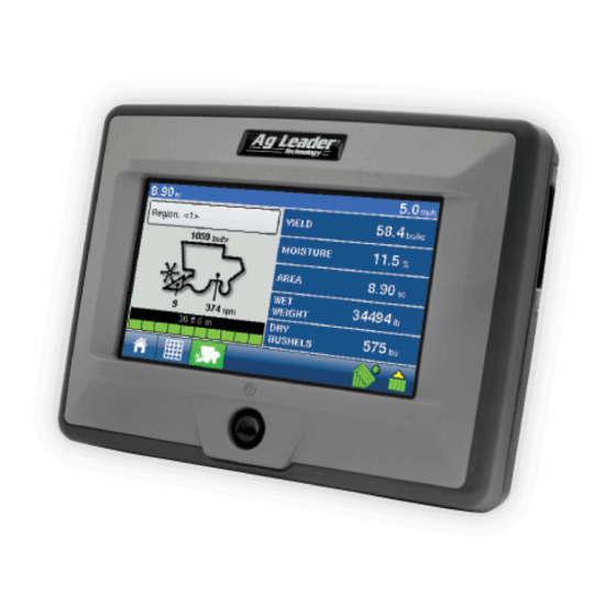
Page 243: Harvest
Harvest Run Time Environment: Map Screen The screens shown below are for a Harvest configuration. In order for you to view the Map Screen, you must first select a Grower, Farm and Field at the Start Field Operation portion of the Home Screen. For more information, See “Management”... -
Page 244: Map Screen: Zoom Detail
EDGE User Manual Map Screen: Zoom Detail When the Map Screen is shown in Zoom Detail, the Vehicle Icon appears as a gold triangle, rather than an arrow. The following Harvest Display items are available at the Map Screen: • Display Legend icon- (For example, see previous page). The Display Legend is only accessible in the Zoom to Extent view. -
Page 245: Harvest Button On Task Bar
Flow Sensor in the Clean Grain Elevator. Because of this time lag, the instananeous coverage is shown on the Map Screen as a lighter color than coverage that has been logged by the EDGE display. For an example, see the picture below. -
Page 246: Run Time Environment: Harvest Screen
EDGE User Manual Run Time Environment: Harvest Screen The Harvest Screen, accessible with the Harvest Button, is where you can view Region Selection, Header Height, Elevator Speed, Swath Width and Display Items. • Region Selection - Displays the current region that you are harvesting, and also used to change regions and flag calibration loads. -
Page 247: Harvest Screen Display Items
EDGE Firmware Version 1.5 Harvest Screen Display Items • Yield - Displays the instantaneous yield while there is grain flow and the average yield when grain flow is not present. • Moisture - Displays the instantaneous moisture while there is grain flow and the average when there is no grain flow. -
Page 248: Harvest Screen - Active Display Items
EDGE User Manual Harvest Screen - Active Display Items The Harvest Screen includes three active display items that if pressed, summon three different screens that display further harvest information. • Region Display Item - Summons the Region Options screen, where you can change Regions, edit a Region Name, or flag a region as a calibration load. -
Page 249: Harvest Setup Tabs
EDGE Firmware Version 1.5 Harvest Setup Tabs Pressing the Harvest button at the Setup Screen takes you to the Grain Harvest Configuration Tab. This tab is shown in front of four other tabs: Combine, Header, Crops and Calibration. • Configuration Tab - The Configuration Tab is where you can add and edit operating configurations. -
Page 250: Create A Harvest Configuration
EDGE User Manual Create a Harvest Configuration To set up a Harvest configuration, you must set up a Combine and Header configuration with the following procedure. 1 At the Setup screen, press the Harvest button. The Configuration Tab opens, as shown below. -
Page 251: Configuration Settings
EDGE Firmware Version 1.5 Configuration Settings By highlighting a configuration and pressing the Wrench button on the Configuration Tab, you can summon the Configuration Settings screen, where you can choose primary and backup speed source, Calibrate Distance, or adjust AutoSwath settings. -
Page 252: Calibrate Distance
EDGE User Manual Calibrate Distance If you are not using GPS for ground speed, then after you have created a configuration you must calibrate the ground speed input for accurate speed and area calculations. If you are using GPS, you still must calibrate distance in the event of GPS loss. -
Page 253: Combine Tab
EDGE Firmware Version 1.5 Combine Tab Underneath the Combine Tab, you can view, add, rename or remove combines, or adjust combine settings. • Press the Add button to add a configuration. • Press the on-screen keyboard to edit or rename existing combines. -
Page 254: Advanced Combine Settings
EDGE User Manual Advanced Combine Settings The Combine Settings button allows you to change the advanced settings for the selected combine. The values should not be changed unless instructed to do so by Ag Leader Technical Support. Note: Do not change any of the advanced combine settings... -
Page 255: Gps Offsets
EDGE Firmware Version 1.5 GPS Offsets After completing the process of setting up a Combine, GPS Offsets must be configured. The GPS Offsets define where machine parameters are in relation to the GPS antenna. These settings are used by mapping and AutoSwath. -
Page 256: Head Offset
EDGE User Manual GPS Offsets (continued) Head Offset The Head Tab allows you to enter in the distance from the head attachment point to the rear axle. Use the numeric keypad to enter in the distance to the axle. PN: 4001662 Rev.A... -
Page 257: Header Tab
EDGE Firmware Version 1.5 Header Tab Underneath the Header Tab, you can view, add, rename or remove headers, or adjust header settings. • Press the Add button to add a header. • Press the on-screen keyboard to edit or rename existing headers. -
Page 258: Header Settings
EDGE User Manual Header Settings Under the Header Tab, highlight the header name, press the Wrench button and go to the Header Settings screen. At the Header Settings screen, you can view the swath width and/or the number of rows on the header, as well as calibrate the Header Sensor and adjust the Header Offset. -
Page 259: Calibrate Header Sensor
EDGE Firmware Version 1.5 Calibrate Header Sensor Prior to logging harvest data, you must calibrate the header sensor. To do this, first press the Header Tab, select the correct header from the Header List and press Calibrate Header Sensor. Note: To calibrate a header sensor, you must have first a crop defined. - Page 260 EDGE User Manual Calibrate Header Sensor (continued) Set Stop Height. Select the correct crop type from the list box. Raise or lower the header to the height where you would like to have the area logging turn on and off. Press Set Height.
-
Page 261: Header Offset
EDGE Firmware Version 1.5 Header Offset If the header of your vehicle is mounted asymmetrically to the vehicle's center, this can affect the accuracy of the GPS data you are receiving. With the Header Offset feature, you can compensate for the distance between the center of the vehicle and the center of the header's swath. -
Page 262: Crops Tab
EDGE User Manual Crops Tab Crops are added and edited on the Crops Tab. The crops list shows all the crops that have been created and are available for use. • Press the Add button to add a crop. • Press the on-screen keyboard to edit or rename existing crops. -
Page 263: Crop Settings
EDGE Firmware Version 1.5 Crops Tab (continued) Crop Settings The Crop Settings screen displays the Dry % and the Weight/Volume for the selected crop. Here you can edit Crop Settings and edit the map legend. • Edit Crop Settings - The Edit Crop Settings button allows you to edit Grain Settings values from the default, such as Dry % and the Weight/Volume settings. -
Page 264: Calibration Tab
The Calibration Tab is where you may perform Weight, Moisture, Vibration and Temperature calibrations. • Weight - The Weight button allows you to enter actual Weight Calibration loads into the EDGE display for each grain type. For more information, See “Grain Weight Calibration” on page 259. -
Page 265: Pre-Harvest Checklist
Distance” on page 242. Calibrate Header Sensor This sets the height when the EDGE display stops recording area as the header is raised at the end of the pass. Stop height calibration is required for each grain type. For more information, See “Calibrate Header Sensor”... -
Page 266: Vibration Calibration
EDGE User Manual Vibration Calibration The vibration calibration must be performed with the correct head on the combine, and repeated for each crop harvested. 1 Run Separator. Start the separator and feeder house with the proper header attached. Run at full speed. -
Page 267: Temperature Calibration
Take Air Temperature Reading. Take an accurate air temperature reading using a thermometer in the same shaded area. Press Temperature Button on Calibration Tab. On the EDGE display, go to the Calibration Tab and press the Temperature button. The Temperature Calibration screen appears, as shown below. -
Page 268: Moisture Calibration
Press Moisture Button on Calibration Tab. On the EDGE display, go to the Calibration Tab. Use the drop-down menu to select the crop to calibrate. Next, press the Moisture button. The Moisture Calibration screen appears, as shown below. -
Page 269: Grain Weight Calibration
Before the EDGE display can accurately measure harvested bushels, you must calibrate the display by entering in actual load weights into the EDGE display for each grain type. You must obtain these actual load weights by weighing the grain from a load on accurate scales. To obtain accurate results, you must obtain between four and six calibration loads. - Page 270 Empty Grain and Weigh Load. Empty the grain tank completely onto a truck or wagon, and weigh it with an accurate scale. Record each individual load weight to be entered into the EDGE display. (No grain from any other combine should be unloaded into this hauling vehicle).
- Page 271 EDGE Firmware Version 1.5 Grain Weight Calibration (continued) Select Crop to Calibrate. Press the Grain Harvest button and then go to the Calibration Tab, as shown below. Use the drop-down menu to select the crop to calibrate. 10 Press Weight Button. Press the Weight button, and the Weight Calibration Screen appears, as shown below.
- Page 272 EDGE User Manual Grain Weight Calibration (continued) 12 Select Region and Enter Actual Weight. The Enter Cal Weight screen appears, as shown below. Select the Region and use the numeric keypad to enter the Actual Weight for those regions. Repeat this step for each calibration load. When finished, press the checkmark button.
- Page 273 In the example below, Region 3 has an error percentage of 21.8 percent. You should be able to calibrate the EDGE display for grain weight to an average error of 1% to 3%. If the average error is more than 3%, uncheck the load with the maximum error.
-
Page 274: Adding A New Calibration
EDGE User Manual Adding a New Calibration If you notice a decreased yield accuracy, you may need to perform a new calibration. To do this, use the following procedure. 1 Select Crop to Calibrate. Press the Grain Harvest button and then go to the Calibration Tab, as shown below. - Page 275 These numbers have been pre-set by Ag Leader Technology, and you should not change them unless instructed to by Ag Leader Technical Support.
- Page 276 EDGE User Manual Adding a New Calibration (continued) Retire Old Calibration. The Retire Calibration warning screen appears, as shown below. Press the checkmark to retire your old calibration. Note: By retiring your old calibration, you will not be able to return to your old calibration, or add data to it.
- Page 277 EDGE Firmware Version 1.5 Adding a New Calibration (continued) Perform New Weight Calibration. After you have created a new calibration, it is recommended that you perform another Weight Calibration. Refer to “Grain Weight Calibration” on page 259 PN: 4001662 Rev.A...
-
Page 278: Diagnostics
EDGE User Manual Diagnostics Pressing the Harvest Display Item on the Harvest Screen summons the Harvest Diagnostics screens that pertain to your configuration (For an example, see illustration at “Harvest Screen - Active Display Items” on ). Technical support may request that you look at these screens page 238 for help in diagnosing a problem. - Page 279 EDGE Firmware Version 1.5 Harvest Diagnostic Notes • For generalized Diagnostic information, such as memory, display, CAN device and firmware version information, See “Diagnostics” on page 39. • For more information on LED diagnostic states, See “Module LED Diagnostic States” on page 277.
- Page 280 EDGE User Manual PN: 4001662 Rev.A...
- Page 281 EDGE Firmware Version 1.5 configuration settings screen 242 Index - Harvest configuration tab 239 keyboard 240 wrench button 240, 241, 242 crop settings 252, 253 antenna tab 245 edit legend 253 legend settings 253 crops bushels per hour 236 add 252...
- Page 282 EDGE User Manual region selection 236 swath width 236, 238 edit crop settings wet weight 237 crop settings yield 237 edit 253 head tab 246 edit legend 253 header add 247 edit name 247 flow delay 235 remove 247 flow max 268...
- Page 283 EDGE Firmware Version 1.5 moisture raw 268 temperature calibration 257 motor current 268 temperature raw 268 new calibration 265 use manual moisture 258 operating configuration wizard 240 vibration 254, 256 vibration calibration 256 pre-harvest checklist 255 proximity sensor 268 weight 254, 264...
- Page 284 EDGE User Manual PN: 4001662 Rev.A...
-
Page 285: Appendix
Appendix This Appendix contains the following: • “System Diagrams Reference” on page 275 • “EDGE File Formats” on page 276 • “Module LED Diagnostic States” on page 277 • “Company Warranty Statement” on page 278 System Diagrams Reference To view detailed system diagrams for various machine configurations, go... -
Page 286: Edge File Formats
Upgrade button on the Console Screen’s Memory Tab. .msf The .msf (Management Setup File ) file format allows the EDGE display to import Grower and Field information from SMS software via a Compact Flash Card. -
Page 287: Module Led Diagnostic States
EDGE Firmware Version 1.5 Module LED Diagnostic States Prescription Map File Description Types No power Flashing 1 Hz green Normal operation Flashing 1 Hz orange CAN bus errors detected (error active/passive state) Steady orange CAN bus off Steady red Hardware or initialization failure... -
Page 288: Company Warranty Statement
WARRANTY Ag Leader Technology will repair or replace at no charge any component of the EDGE system that fails during normal service, while being used in an approved application, within two years of the warranty start date. Warranty is not provided for damage resulting from abuse, neglect, accidents, vandalism, acts of nature, or any causes that are outside of the normal intended use of the EDGE system.
Need help?
Do you have a question about the EDGE and is the answer not in the manual?
Questions and answers