
Related Manuals for Klimawent UFO-A-5000


Summary of Contents for Klimawent UFO-A-5000
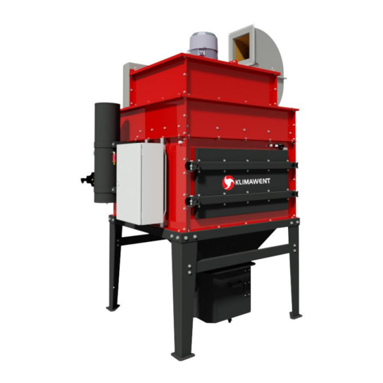
- Page 1 Use and Maintenance Manual UFO-A-5000 Filtering unit 24.05.2019 Filtering unit UFO-A-5000...
-
Page 2: Table Of Contents
Assembly and Start-up ................ 9 Operational Use .................. 12 Troubleshooting Guide ................ 27 Maintenance ..................27 Occupational Health and Safety ............29 Transport and Storage ................ 29 Terms of warranty ................29 Sample of the Declaration of Conformity ..........30 Filtering unit UFO-A-5000 24.05.2019... -
Page 3: Introductory Remarks
The construction of the UFO-A-5000 filtering unit meets the requirements of the current state of technology as well as the safety and health assurances included in: ... -
Page 4: Application
UFO-A-5000 filtering unit is manufactured in two versions UFO-A-5000 RH with the air outlet on the right side and UFO-A-5000 LH with the air outlet on the left . The device is designed for cleaning the air from the impurities arising during manufacturing processes. The appliance is... - Page 5 – diameter Ø12 mm (quick-connector) Fig. No.1 – Flow chart Table No.2 – Replaceable parts – Cartridge filter – 2 pieces Type Weight Filtration efficiency Remarks [kg] Replacement frequency: PN206638U 99,9 1 up to 2 years. 24.05.2019 Filtering unit UFO-A-5000...
-
Page 6: Structure And Function
Fig. No.2 – Additional element – Fan cover OW-UFO-A-5000 – fan cover to be installed on the device 5. Structure and Function UFO-A-5000 filtering unit is constructed of subsequent operational assemblies: Fan in a sound-absorbing housing Filtration chamber – as a middle part of the device, contains two cartridge filters. The cham- ber housing is equipped with an inspection door for filter replacement. - Page 7 (see Fig. No.2). Filtering units with a free (not plugged) outlet should be equipped with an air guide KP-UFO-A-5. Fig. No.3a – UFO-A-5000 RH (with the air inlet on the right side) – dimensions 24.05.2019 Filtering unit UFO-A-5000...
- Page 8 Fig. No.3b – UFO-A-5000 LH (with the air inlet on the left side) – dimensions Filtering unit UFO-A-5000 24.05.2019...
-
Page 9: Assembly And Start-Up
Switchgear – to operate the fan, and (depending on the time programme) controls the elec- tromagnetic valves. It is delivered along with the device. On one of the rear legs, there is fastened a clamp to connect the UFO-A-5000 with the local equilibrating profile. - Page 10 For example: UFO-A-10000 of nominal flow 10000 m /h, its /h – that provides extraction for real volume flow during plasma cutting will be 5000 m one table segment of dimensions 2100 x 500 mm. Filtering unit UFO-A-5000 24.05.2019...
- Page 11 2. On demand of Customer the filtering unit can be equipped with an activated carbon impreg- nated nonwoven (spunbond) filter – for filtering the gases arising during welding processes. Fig. No.5 – Connection Diagram UFO-A-5000 24.05.2019 Filtering unit UFO-A-5000...
-
Page 12: Operational Use
7. Operational Use UFO-A-5000 has been developed for cooperation with a system of local exhausts, for example extraction arms, connected to the main ducting that is joining them with the inlet fitting pieces. The ZE-UFO-A switchgear is delivered along with the appliance and controls the device fun- ction providing cleaning of the filters surfaces by cyclical impulses of compressed air. - Page 13 Fig. No.6 – Switchgear – front Fig. No.7 – Control panel 24.05.2019 Filtering unit UFO-A-5000...
- Page 14 – B1 – controller UFOv5.1 – controls the function of the electromagnetic valves – supervisory relay CKF – time relay K1T – keyboard – terminal strip Fig. No.8 – Switchgear – inside Fig. No.9 – Time chart of work regimes Filtering unit UFO-A-5000 24.05.2019...
- Page 15 OK – correct state of the functional elements of the board UFOv5.1 EO1 – alarm of the memory of the data EO2 – alarm of the sensor of the temperature measuring EO3 – alarm of the RTC clock 24.05.2019 Filtering unit UFO-A-5000...
- Page 16 MANUAL – mode of continuous work PROG – mode of work as a function of time programmer Screen MODES MODES -> Sub-menu of the setting groups MODES Screen SETTINGS SETTINGS -> Sub-menu of the adjustments group SETTINGS Filtering unit UFO-A-5000 24.05.2019...
- Page 17 Screen INPUTS / OUTPUTS INPUTS / -> Sub-menu of the settings INPUTS / OUTPUTS OUTPUTS Screen SETTING OF TIME Day = Tu hour 10:00 To adjust the days of the week and the time Lang = PL 24.05.2019 Filtering unit UFO-A-5000...
- Page 18 COOL – activated function of cooling by means of the output OUT5 [AL24V akt.]:{OFF I ON} OFF – blocking of the occurring alarm in case of lack of the suppor- ting power supply 24VAC for outputs of electro-valves T1÷T4 ON – alarm AL24V activated Filtering unit UFO-A-5000 24.05.2019...
- Page 19 OFF – blocking of the possibility of switching on by means of the input DI5 of the status NSTR ON – stop of the status NSTR active Input DI4 makes the same function as the button START S1 on the elevation console 24.05.2019 Filtering unit UFO-A-5000...
- Page 20 NSTR (switching on within the level) ON – stop of the status NSTR active (switching on within the level) In case when [DI8. START]=ON and [DI8stop]=ON input DI8 fulfils the function of remote control ON / OFF of the status NSTR Filtering unit UFO-A-5000 24.05.2019...
- Page 21 Ton PowPause = 10s Time T12 – duration of the impulse of the supply of the electro-valves [TonPowPause]:{1 - 50 sec} TonPowPause – duration of the status STB (initialising of the system after the power supply is switched on) 24.05.2019 Filtering unit UFO-A-5000...
- Page 22 Time T22 – duration of the break (idle time) between the impulses of the power supply of the electro-valves, during the status SKF [Lsekwen Loff]:{0-20} Lsekwen Loff – number of sequences (4 cycles of pulsing each) – of pulsing – for the status SKF Filtering unit UFO-A-5000 24.05.2019...
- Page 23 AktPozimWe – the level of signal (from the input of pressure control) is active Screen SETTINGS 6/6 Tset = 21 [Tset]:{10÷60} Tset – the applied temperature for the controlling with heating or cooling – depending on the parameter [TEMP REG] 24.05.2019 Filtering unit UFO-A-5000...
- Page 24 (TO) – status of the outputs of impulses T1-T4 Screen INPUTS / OUTPUTS 3/3 Tb=+25.5 StanZas 24 = OK (Tb) – measuring of temperature on the controller (StanZas 24V) – the state of transformer fuse 24VAC of the power supply of the electromagnetic valves Filtering unit UFO-A-5000 24.05.2019...
- Page 25 DOUT5 of the controller (Screen MODES 2/6, Screen SETTINGS 6/6, Screen INPUTS / OUTPUTS 1/3 and 3/3 24.05.2019 Filtering unit UFO-A-5000...
- Page 26 Screen MODES 2/6. High efficiency and filter cleaning executed by the automatic filter regeneration system (repea- ted air impulses) provide long durability and reliable function of the filter cartridges and limits its maintenance to the minimum. Filtering unit UFO-A-5000 24.05.2019...
-
Page 27: Troubleshooting Guide
Upon every emptying of the waste container (under the hopper), examine visually the state of the cartridge filters. First disconnect the power supply. Through the front revision door, check the mounting correctness of the elements , the state of the filtration surface, pollution degree, search for failures, etc. 24.05.2019 Filtering unit UFO-A-5000... - Page 28 General visual inspection of the supporting structure and the housing, check the screw connections. Every 12 months Examine the state of electrical connections and the installation of the compressed air, the connections of the electromagnetic valves. Filtering unit UFO-A-5000 24.05.2019...
-
Page 29: Occupational Health And Safety
11. Transport and Storage The UFO-A-5000 filtering unit has to be transported in two assemblies in foil, placed on transport pallets. For the transport time the device should be kept in vertical position and protected from an uncontrolled overturn and displacement / slide. -
Page 30: Sample Of The Declaration Of Conformity
Declaration of conformity EC No. …………….. Manufacturer (eventually the authorized representative / importer): name: KLIMAWENT S.A. address: 81-571 Gdynia, Chwaszczyńska 194 A person, authorized for issuing the technical documentation: Teodor Świrbutowicz, KLIMAWENT S.A. hereby declares that the appliance: name: Filtering unit... - Page 31 NOTES: 24.05.2019 Filtering unit UFO-A-5000...
- Page 32 Producer: KLIMAWENT S.A. 81-571 Gdynia, ul. Chwaszczyńska 194 tel. 058 629 64 80 fax 058 629 64 19 e-mail: klimawent@klimawent.com.pl www.klimawent.com.pl 804U17 UFO-A-5000 RH 24.05.2019/EN 804U22 UFO-A-5000 LH 24.05.2019/EN Filtering unit UFO-A-5000 24.05.2019...
Need help?
Do you have a question about the UFO-A-5000 and is the answer not in the manual?
Questions and answers