Table of Contents
Advertisement
Advertisement
Table of Contents

Related Manuals for TEXA TMD MK3 DIAG


Summary of Contents for TEXA TMD MK3 DIAG
- Page 1 ENGLISH..............5...
-
Page 3: Table Of Contents
4.2.6 Fire and Explosion Hazard...............12 4.2.7 Noise Hazard....................12 4.2.8 High Voltage Hazard.................12 4.2.9 Poisoning Hazard..................13 4.3 General User and Maintenance Warnings...........14 5 SPECIFIC SAFETY RULES FOR USING TMD MK3 DIAG....15 5.1 Glossary....................15 5.2 General Rules..................15 5.3 Operator Safety..................16 5.4 Device Safety..................16 6 OPERATION OF THE RADIO DEVICES..........18... - Page 4 12.1 Precautions..................24 12.2 Installation..................24 13 USE....................29 14 MAINTENANCE................30 15 BLINK CODES ................31 16 TROUBLESHOOTING..............32 17 TECHNICAL CHARACTERISTICS..........33 18 ENVIRONMENTAL INFORMATION..........35 19 LEGAL NOTICES................36...
-
Page 5: Review Of The Manual
TMD MK3 DIAG TECHNICAL MANUAL Review of the Manual This document is review 02 of the TMD MK3 DIAG technical manual. -
Page 6: Introduction
INTRODUCTION Dear Customer, We would like to thank you for choosing a TEXA product for your workshop. We are certain that you will get the greatest satisfaction from it and receive a great deal of help in your work. Please read through the instructions in this manual carefully and keep it for future reference. -
Page 7: About The Manual
Regulatory information: it gives indications regarding the laws that are applied to the device this document refers to. TMD MK3 DIAG: it gives a brief overview of the device this document refers to. Description: it describes the main features of the device this document refers to. -
Page 8: Legend Of The Symbols Used
2 LEGEND OF THE SYMBOLS USED The symbols used in the manual are described in this chapter. Asphyxiation Risk Explosion Risk High Voltage Hazard Fire / Burn risk Poisoning Hazard Corrosive Substances Risk Noise Hazard Moving Parts Risk Crushing Risk General Risk Important information... -
Page 9: Glossary
3 GLOSSARY This chapter provides the meaning of the technical terms used in the manual: Diagnosis/diagnostic socket: female connector installed in the vehicle that • allows connecting to the vehicle's control unit. • OBD socket: diagnostic socket specific for the OBD protocol. Diagnosis/diagnostic connector: male connector installed in the diagnostic tool •... -
Page 10: General Safety Regulations
4 GENERAL SAFETY REGULATIONS 4.1 Glossary • Operator: qualified individual, in charge of using the device/tool. Machine/device/tool: the product purchased. • Workplace: the place where the operator must carry out her/his work. • 4.2 Operator Safety Regulations 4.2.1 General Safety Regulations The operator must be completely clear-headed and sober when using the device;... -
Page 11: Hazards Caused By Moving Parts
Safety Precautions: Always make sure that the vehicle is in neutral gear (or that it is set in parking • position in case of a vehicle equipped with automatic transmission). Always activate the hand brake or parking brake on the vehicle. •... -
Page 12: Fire And Explosion Hazard
4.2.6 Fire and Explosion Hazard The following are potential fires and/or explosion hazards: The types of fuel used by the vehicle and the vapours released by these • fuels. The refrigerants used by the A/C system. • The acid in the vehicle batteries. •... -
Page 13: Poisoning Hazard
Work with dry hands only. • • Keep conductive liquids away from the engine while working. Never leave tools on the battery in order to avoid accidental contacts. • 4.2.9 Poisoning Hazard The hoses used to extract the refrigerants can release toxic gases, dangerous to the operator if exposed to temperatures higher than 250 °C or in case of a fire. -
Page 14: General User And Maintenance Warnings
4.3 General User and Maintenance Warnings When using the device or carrying out scheduled maintenance (eg. fuse replacement) on the device, carefully follow the information provided below. Do not remove or damage the labels/tags and the warnings on the device; do •... -
Page 15: Specific Safety Rules For Using Tmd Mk3 Diag
DIAG diagnostic tools means that they are reliable, simple and safe to use. Personnel in charge of using diagnostic tools are required to follow the general safety regulations, to use TMD MK3 DIAG devices for their intended use only, and to carry out maintenance correctly as described in this manual. -
Page 16: Operator Safety
5.3 Operator Safety Some self-diagnosis operations allow you to activate/deactivate certain actuators and safety systems on the vehicle. Safety Measures: In order to avoid injuring people and/or damaging the device or the electronic • systems of the vehicle connected to the device, do not allow unqualified personnel to use the device. - Page 17 If not otherwise specified, use the tool on vehicles with a 12 V DC power supply • and chassis connected to the negative pole. • Do not use external batteries to supply the tool unless explicitly requested to do so by the software. The electromagnetic compatibility tests carried out on the device guarantee that it can be adapted to the technologies normally used on vehicles (ex.: engine control, ABS, airbag, etc.).
-
Page 18: Operation Of The Radio Devices
6 OPERATION OF THE RADIO DEVICES Wireless connection with Bluetooth® technology The wireless connection with Bluetooth technology is a technology that supplies a standard and reliable method to exchange information between different devices, using radio waves. Products such as cellular phones, portable devices, computers, printers, cameras, pocket PCs etc. -
Page 19: Normative Information
7 NORMATIVE INFORMATION Declaration of Conformity Texa S.p.A. hereby declares that this TMD MK3 DIAG device complies with the essential requirements and with all further provisions defined by the R&TTE 1999/5/EC and RoHS 2011/65/EU directives. A complete copy of the Declaration of Conformity can be found at... -
Page 20: Tmd Mk3 Diag
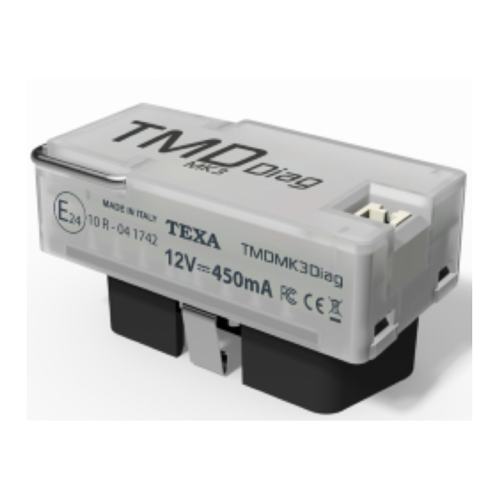
8 TMD MK3 DIAG TMD MK3 DIAG is a small device capable of acquiring data while driving via the vehicle OBD socket on which it is installed. Connecting the TMD MK3 DIAG and disconnecting it from the vehicle is quick and easy. -
Page 21: Description
9 DESCRIPTION This chapter describes the general features of the device. Status LEDs: they give indications regarding the status of the device.* • Green: indicates the status of the device without Bluetooth communication. Red: indicates the presence of errors. • Extraction hook: it allows you to remove the device easily. -
Page 22: Power Supply
10 POWER SUPPLY The device is designed to be used ONLY on vehicles with 12 V power supply and chassis connected to the negative pole. The device draws its power supply directly from the battery of the vehicle it is connected to through the OBD socket. -
Page 23: Location Of The Diagnostic Socket
11 LOCATION OF THE DIAGNOSTIC SOCKET The images below indicate where the diagnostic socket may be located. The percentages indicated in each image refer to how often each location is used by the manufacturer. We always recommend you check the location of the OBD socket in the vehicle's user manual. -
Page 24: Installation
12 INSTALLATION The following chapters illustrate how to install the device. The installation must be performed by qualified personnel only. 12.1 Precautions Make sure that all wirings and cables in general and the hydraulic pipes of both fuel and safety pneumatic devices do not suffer from any damage during installation. - Page 25 A screwdriver may be needed to loosen the screws that fasten the panels that cover the OBD socket. Make sure the vehicle is off (instrument panel off) when connecting and disconnecting the device from the OBD socket. Proceed as follows: 1.
- Page 26 Choose the length of the string carefully, based on the position of the OBD socket. Make sure it does not interfere with the use of the clutch, brake or accelerator or other devices within the vehicle required for safety reasons or a normal operation of the vehicle itself, as specified by the car manufacturer.
- Page 27 11. Make sure the device is securely connected to the diagnostic socket to avoid it from accidentally disconnecting during use. 12. Turn on the vehicle (instrument panel on). 13. Wait for the LED to flash. Make sure that the position of the device does not interfere with driving.
- Page 28 NOTE: Device removal You might have to disconnect the device form the OBD socket during vehicle maintenance operations in order to allow the connection of diagnostic devices. Proceed as follows: 1. Turn off the vehicle (ignition key off). 2. Carefully remove any panels cover the OBD socket. 3.
-
Page 29: Use
13 USE It is no longer required to act directly on the device after the installation and configuration. The device activates as soon as the vehicle's instrument panel is switched on. While driving, do not get distracted to check the status of the device or to interact with it directly or indirectly. -
Page 30: Maintenance
14 MAINTENANCE This product does not require maintenance operations. Follow the indications in this manual carefully in order to guarantee an extended use of the device. In case of doubts or for further information, contact the Technical Assistance or your Service Partner / Retailer. -
Page 31: Blink Codes
15 BLINK CODES The bi-colour LED (green/red) on the device flashes to indicate the various states of the device itself, both while it is connecting to the display unit and when it is connecting to the vehicle. The BLINK CODE of the LED is indicated in the table below. DURATION STATUS GREEN... -
Page 32: Troubleshooting
16 TROUBLESHOOTING Below there are some situations / problems that can occur while using the device, along with a possible cause and a possible solution. Situation / Problem Possible Cause Possible Solution Carefully disconnect and device reconnect the device to properly connected and diagnostic socket... -
Page 33: Technical Characteristics
CAN LS ISO11898-3 • Power Supply Supports 12 V vehicles • vehicle ON: absorption with TMD MK3 DIAG only = 80 mA • Consumption maximum absorption (with TMD MK3 EDR connected • to the J3 connector) = 450 mA vehicle OFF: 3 mA •... - Page 34 R&TTE 1999/05/EC Directives RoHS 2011/65/EU EN 301 489-1V1.9.2:2011 EN 301 489-17V1.6.1:2013 EN 300 328-2V1.8.1:2012 Product EN 60950-1:2006 + A11:2009 + A1:2010 + A12:2011 + AC: standards 2011 + A2:2013 ISO 7637-1:2002 ISO 7637-2:2011 Regulations ECE / ONU R10...
-
Page 35: Environmental Information
18 ENVIRONMENTAL INFORMATION For information regarding the disposal of this product please see the pamphlet supplied. -
Page 36: Legal Notices
19 LEGAL NOTICES TEXA S.p.A. Via 1 Maggio, 9 - 31050 Monastier di Treviso - ITALY Cod. Fisc. - No. of Companies' Register of Treviso - Part. IVA: 02413550266 Single member company and subject to management and co-ordination of Opera Holding S.r.l.
Need help?
Do you have a question about the TMD MK3 DIAG and is the answer not in the manual?
Questions and answers