Sign In
Upload
Manuals
Brands
Lenze Manuals
Control Unit
ECSEP Series
Lenze ECSEP Series Manuals
Manuals and User Guides for Lenze ECSEP Series. We have
2
Lenze ECSEP Series manuals available for free PDF download: Operating Instructions Manual, Mounting Instructions
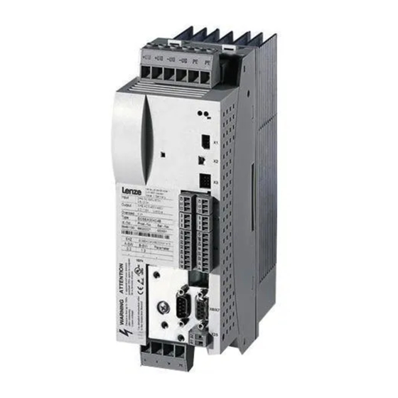
Lenze ECSEP Series Operating Instructions Manual (455 pages)
Axis module "Posi & Shaft"
Brand:
Lenze
| Category:
Control Unit
| Size: 4 MB
Table of Contents
Table of Contents
5
1 Preface and General Information
12
About These Operating Instructions
12
Terminology Used
13
Code Descriptions
14
Features of the Ecsxp Axis Module
15
Scope of Supply
16
Legal Regulations
17
2 Safety Instructions
18
General Safety and Application Notes for Lenze Controllers
18
Thermal Motor Monitoring
22
Forced Ventilated or Naturally Ventilated Motors
23
Self−Ventilated Motors
24
Residual Hazards
26
Safety Instructions for the Installation According to UL
28
Notes Used
29
3 Technical Data
30
General Data and Operating Conditions
30
Rated Data
32
Current Characteristics
34
Increased Continuous Current Depending on the Control Factor
34
Device Protection by Current Derating
37
4 Mechanical Installation
38
Important Notes
38
Mounting with Fixing Rails (Standard Installation)
39
Dimensions
39
Mounting Steps
40
Mounting with Thermal Separation (Push−Through Technique)
41
Dimensions
42
Mounting Steps
44
Mounting in Cold−Plate Design
45
Dimensions
46
Mounting Steps
47
5 Electrical Installation
48
Installation According to EMC (Installation of a Ce−Typical Drive System)
48
Power Terminals
51
Connection to the DC Bus (+UG, −UG)
54
Connection Plan for Mimimum Wiring with Internal Brake Resistor
56
Connection Plan for Mimimum Wiring with External Brake Resistor
58
Motor Connection
60
Motor Holding Brake Connection
61
Connection of an Ecsxk
63
Control Terminals
64
Digital Inputs and Outputs
68
Analog Input
69
Safe Torque off
70
Automation Interface (AIF)
79
Wiring of System Bus (CAN)
80
Wiring of the Feedback System
85
Resolver Connection
86
Encoder Connection
87
Digital Frequency Input/Output (Encoder Simulation)
90
6 Commissioning
92
Basic Terms of Positioning
92
Positioning
92
Touch Probe Positioning
93
Positioning Profile
94
Positioning Profile Mode
95
Additional Functions of the Positioning Profile (C3096/X)
96
Positioning Profile Parameters
97
Setting of Manual Jog (Inching Mode)
101
Homing
101
Measuring System for Positioning
102
Machine Parameters
103
Electrical Shaft ("Eshaft")
107
Device Structure and Interfaces to the Higher−Level Control
108
State Control of the Positioning Drive
110
Operating States
111
Conditions for State Change (Transitions)
113
Before You Start
115
Commissioning Steps (Overview)
116
Basic Settings with GDC
117
Set Reference
119
Setting of Manual Jog (Inching Mode)
121
Setting of Homing
122
Setting Absolute Positioning/Relative Continuous Positioning
123
Loading the Lenze Setting
125
Setting of Mains Data
126
Selecting the Function of the Charging Current Limitation
126
Setting the Voltage Thresholds
127
Entry of Motor Data for Lenze Motors
128
Holding Brake Configuration
130
Setting of the Feedback System for Position and Speed Control
132
Resolver as Position and Speed Encoder
133
Resolver as Absolute Value Encoder
135
Ttl/Sincos Encoder as Position and Speed Encoder
136
Ttl/Sincos Encoder as Position Encoder and Resolver as Speed Encoder
140
Absolute Value Encoder as Position and Speed Encoder
145
Absolute Value Encoder as Position Encoder and Resolver as Speed Encoder
150
Select Control Interface (Operating Mode)
155
Process Data to the Axis Module (Control Word Ctrl1 and Setpoints)
158
Control Word Ctrl1
159
Setpoint Data Words to the Controller (Veldirect, Posdirect, Rx_Par1
160
Process Data from the Axis Module (Status Words and Actual Values)
161
Status Word 1 (Stat1), Status Word 2 (Stat2)
161
Device Status
163
Monitor Data Words from the Controller (Tx_Par1 und Tx_Par2)
164
Entry of Machine Parameters
165
Configuring the Digital Inputs and Outputs
168
Digital Inputs for Operation with Continuous Positioning Axis
170
Digital Inputs for Operation with Linear Positioning Axis
171
Setting the Polarity of Digital Inputs and Outputs
172
Setting of Manual Control Parameters
173
Manual Control to Software Limit Position
175
Manual Control to Hardware Limit Switch
175
Retracting from Hardware Limit Switches
176
Setting of Homing Parameters
177
Setting Homing Modes
179
Shifting the Zero Position with Regard to the Home Position (Offsets C3011, C3012)
187
Example: Reference Search with Linear Positioning Axis
188
Example: Reference Search with Continuous Positioning Axis
189
Setting the Positioning Profile
191
Selecting a Positioning Profile Mode
191
Point−To−Point" Positioning
193
Touch Probe Positioning
194
Continuous Constant Travel
195
Electrical Shaft ("E−Shaft") Per Digital Frequency, Motionbs (CAN) or Ethercat
196
Homing
197
Direct Positioning
198
Positioning Sequence for Controller Optimisation
200
Setting of Positioning Profile Parameters
201
Setting the Profile Parameter Jerk Time for S−Shaped Ramps
202
Additional Functions of the Positioning Profile (C3096/X)
204
Activating the Speed Override
205
Activating the Torque Limitation after Positioning
208
Activating the Profile Continuation Function
209
Activate Immediate Profile Change During Positioning (Direct Change)
210
Configuring the Electrical Shaft ("E−Shaft")
211
Setting the Stretch Factor (C3097 / C3098)
212
Electrical Shaft Via Classical Digital Frequency Coupling (Digital Frequency Input X8)
215
Electrical Shaft Via Motionbus (CAN) with Ecsxp as Electrical Shaft Master
217
Electrical Shaft Via Motionbus (CAN) with PLC as Electrical Shaft Master
220
Electrical Shaft Via Ethercat with PLC as Electrical Shaft Master
224
Starting Positioning Profiles (Profenable, Profile Number)
226
Start of Positioning Profile Via the "Profenable" Control Bit
227
Start of Positioning Profile by Selecting a New Profile Number "Pnoset_X
228
Setting the Target Position Window (Intarget)
229
Defining the Window for Standstill Message
231
Defining the Dwell Time
232
Following Error Monitoring (C3030, C3031)
233
E−Shaft: Speed−Dependent Angular Trimming
235
Software Limit Positions, Limitation of the Travel Range
237
Evaluation of Hardware Limit Switches
240
Controller Enable (CINH = 0)
241
Quick Stop (QSP)
243
Operation with Motors from Other Manufacturers
244
Entering Motor Data Manually
244
Checking the Direction of Rotation of the Motor Feedback System
246
Adjusting Current Controller
247
Effecting Rotor Position Adjustment
249
Optimising the Drive Behaviour after Start
252
Speed Controller Adjustment
252
Adjustment of Field Controller and Field Weakening Controller
254
Resolver Adjustment
257
7 Parameter Setting
258
General Information
258
Parameter Setting with "Global Drive Control" (GDC)
259
Parameter Setting with the XT EMZ9371BC Keypad
260
Connecting the Keypad
260
Description of the Display Elements
261
Description of the Function Keys
263
Changing and Saving Parameters
264
8 Configuration
265
Configuring Motionbus/System Bus (CAN)
266
Setting CAN Node Address and Baud Rate
266
Individual Addressing
271
Defining Boot−Up Master in the Drive System
273
Setting of Boot−Up Time/Cycle Time
274
Executing a Reset Node
276
Guiding Angle Selection and Synchronisation Via Motionbus (CAN)
277
Axis Synchronisation (CAN Synchronisation)
278
Monitoring of the Synchronisation (Sync Time Slot)
281
Axis Synchronisation Via CAN
282
Axis Synchronisation Via Terminal X6/DI1
283
Node Guarding
284
Diagnostics Codes
286
CAN Bus Status (C0359/C2459)
286
CAN Telegram Counter (C0360/2460)
287
CAN Bus Load (C0361/2461)
288
Remote Parameterisation (Gateway Function)
289
9 Monitoring Functions
291
Fault Responses
292
Overview of Monitoring Functions
293
Configuring Monitoring Functions
297
Monitoring Times for Process Data Input Objects
297
Time−Out Monitoring for Activated Remote Parameterisation
299
Short Circuit Monitoring (OC1)
300
Earth Fault Monitoring (OC2)
300
Motor Temperature Monitoring (OH3, OH7)
301
Heatsink Temperature Monitoring (OH, OH4)
303
Monitoring of Internal Device Temperature (OH1, OH5)
304
Function Monitoring of Thermal Sensors (H10, H11)
305
Current Load of Controller (I X T Monitoring: OC5, OC7)
306
Current Load of Motor (I2 X T Monitoring: OC6, OC8)
309
DC−Bus Voltage Monitoring (OU, LU)
313
Voltage Supply Monitoring − Control Electronics (U15)
316
Motor Phase Failure Monitoring (LP1)
316
Monitoring of the Resolver Cable (Sd2)
317
Motor Temperature Sensor Monitoring (Sd6)
318
Monitoring of the Absolute Value Encoder Initialisation (Sd7)
319
Sin/Cos Signal Monitoring (Sd8)
320
Monitoring of the Speed System Deviation (Nerr)
321
Monitoring of Max. System Speed (NMAX)
322
Monitoring of the Rotor Position Adjustment (PL)
323
10 Diagnostics
324
Diagnostics with Global Drive Control (GDC)
324
Diagnostics with Global Drive Oscilloscope (GDO)
326
GDO Buttons
327
Diagnostics with GDO
328
Diagnostics with the XT EMZ9371BC Keypad
333
Diagnostics with Pcan−View
334
Monitoring of Telegram Traffic on the CAN Bus
334
Setting All CAN Nodes to the "Operational" Status
336
Fault Analysis with the History Buffer
338
11 Troubleshooting and Fault Elimination
341
Fault Analysis
341
Malfunction of the Drive
342
Fault Messages
343
Reset Fault Messages (TRIP−RESET)
352
12 Appendix
353
Code Table
353
General Information about the System Bus (CAN)
411
Communication with Motionbus/System Bus (CAN)
412
Communication Phases of the CAN Network (NMT)
414
Process Data Transfer
417
Parameter Data Transfer
423
Addressing of the Parameter and Process Data Objects
429
Overview of Accessories
431
Connector Sets
431
Components for Operation and Communication
432
Brake Resistor
433
Mains Chokes
436
RFI Filters
437
13 Index
438
Advertisement
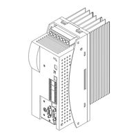
Lenze ECSEP Series Mounting Instructions (200 pages)
Panel-mounted axis module
Brand:
Lenze
| Category:
Control Unit
| Size: 1 MB
Table of Contents
Deutsch
6
Table of Contents
6
1 Über diese Dokumentation
7
2 Sicherheitshinweise
8
Allgemeine Sicherheits− und Anwendungshinweise für Lenze−Antriebsregler
8
Motor Thermisch Überwachen
12
Fremdbelüftete oder Selbstgekühlte Motoren
14
Eigenbelüftete Motoren
16
Restgefahren
19
Sicherheitshinweise für die Installation nach UL
21
3 Technische Daten
22
Allgemeine Daten und Einsatzbedingungen
22
Bemessungsdaten
24
4 Mechanische Installation
26
Wichtige Hinweise
26
Montage mit Befestigungsschienen (Standard−Einbau)
27
Abmessungen
27
Montageschritte
28
5 Elektrische Installation
29
Emv−Gerechte Installation (Aufbau des Ce−Typischen Antriebssystems)
29
Leistungsanschlüsse
32
Anschluss an den DC−Zwischenkreis (+UG, −UG)
35
Anschluss Motor
38
Anschluss Motorhaltebremse
39
Steueranschlüsse
41
Digitale Eingänge und Ausgänge
45
Analog−Eingang
46
Sicher Abgeschaltetes Moment
48
Systembus (CAN) Verdrahten
54
Rückführsystem Verdrahten
58
Anschluss Resolver
59
Anschluss Encoder
60
(Encoder−Nachbildung)
64
6 Installation Überprüfen
67
English
70
1 About this Documentation
71
2 Safety Instructions
72
General Safety and Application Notes for Lenze Controllers
72
Thermal Motor Monitoring
76
Forced Ventilated or Naturally Ventilated Motors
78
Self−Ventilated Motors
80
Residual Hazards
83
Safety Instructions for the Installation According to UL
85
3 Technical Data
86
General Data and Operating Conditions
86
Rated Data
88
4 Mechanical Installation
90
Important Notes
90
Mounting with Fixing Rails (Standard Installation)
91
Dimensions
91
Mounting Steps
92
5 Electrical Installation
93
Installation According to EMC (Installation of a Ce−Typical Drive System)
93
Power Terminals
96
Connection to the DC Bus (+UG, −UG)
99
Motor Connection
103
Motor Holding Brake Connection
104
Control Terminals
106
Digital Inputs and Outputs
110
Analog Input
111
Safe Torque off
113
Wiring of System Bus (CAN)
119
Wiring of the Feedback System
123
Resolver Connection
124
Encoder Connection
125
Digital Frequency Input/Output (Encoder Simulation)
129
6 Installation Check
132
Français
137
1 Présentation du Document
138
2 Consignes de Sécurité
139
Instructions Générales de Sécurité Et D'utilisation Relatives Aux Variateurs Lenze
139
Surveillance de la Température du Moteur
143
Moteurs Avec Motoventilation Ou Refroidissement Naturel
145
Moteurs Avec Autoventilation
147
Dangers Résiduels
150
Consignes de Sécurité Pour L'installation Selon UL
152
3 Spécifications Techniques
153
Caractéristiques Générales Et Conditions D'utilisation
153
Caractéristiques Assignées
155
4 Installation Mécanique
157
Remarques Importantes
157
Montage Avec Profilés de Fixation (Montage Standard Sur Panneau)
158
Encombrements
158
Opérations de Montage
159
5 Installation Électrique
160
Câblage Conforme CEM (Installation D'un Système D'entraînement CE)
160
Partie Puissance
163
Raccordement du Bus CC (+UG, −UG)
166
Raccordement du Moteur
169
Raccordement du Frein de Parking
170
Partie Commande
172
Entrées Et Sorties Numériques
176
Entrée Analogique
177
Absence Sûre de Couple
179
Câblage du Bus Système (CAN)
185
Câblage du Système de Bouclage
189
Raccordement du Résolveur
190
Raccordement du Codeur
191
Entrée/Sortie Fréquence Maître (Émulation Codeur)
195
6 Vérification de L'installation
198
Advertisement
Related Products
Lenze ECSEA Series
Lenze ECSEK Series
Lenze ECSEK001
Lenze ECSEK002
Lenze ECSES Series
Lenze ECSE 004 Series
Lenze ECSE 008 Series
Lenze ECSE 016 Series
Lenze ECSE 064 Series
Lenze ECSE 048 Series
Lenze Categories
DC Drives
Control Unit
Inverter
Engine
Controller
More Lenze Manuals
Login
Sign In
OR
Sign in with Facebook
Sign in with Google
Upload manual
Upload from disk
Upload from URL