Table of Contents
Advertisement
Quick Links
Description
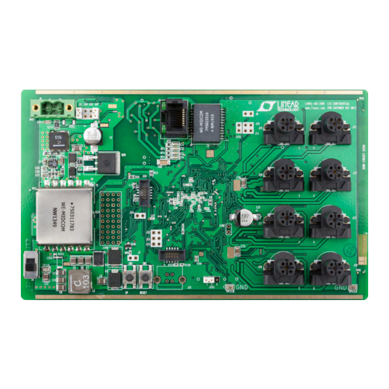
Demonstration circuit 2228A is a complete 8-port IO-Link
Master that uses two
LTC
IO-Link v1.1 physical interface (PHY). DC2228A operates
either with an external supply V
(PoE) system. The IO-Link stack protocol runs on an
NXP microcontroller. A software Control Tool operates
the DC2228A.
performance summary
SYMBOL
PARAMETER
V
Input Supply Range
DD
----
PoE Supply Range
VS
Supply Voltage for Devices
M
IS
Supply Current for Devices
M
ISIR
Current Pulse Capability for Devices
M
BoarD photo
2874
IC's to implement its
®
or a Power over Ethernet
DD
Specifications are at T
CONDITIONS
J5; S1 in EXT Position
J1; S1 in PoE Position; LTPoE ++ 90W
V(L+) > 18V
DEMO MANUAL DC2228A
8-Port IO-Link Master
Reference Design
Design files for this circuit board are available at
®
http://www.linear.com/demo/DC2228A
L, LT, LTC, LTM, Linear Technology and the Linear logo are registered trademarks and Hot
Swap and LTPoE ++ are trademarks of Linear Technology Corporation. IO-Link is a registered
trademark of PROFIBUS Nutzerorganisation (PNO) e.V. All other trademarks are the property of
their respective owners. Compatible with IO-Link Consortium as set forth by PROFIBUS PNO.
= 25°C
A
LTC2874
MIN
TYP
MAX
UNITS
20
30
41
57
20
30
200
500
dc2228af
V
V
V
mA
mA
1
Advertisement
Table of Contents

Related Manuals for Linear Technology LTC2874


Summary of Contents for Linear Technology LTC2874
- Page 1 ® IO-Link v1.1 physical interface (PHY). DC2228A operates L, LT, LTC, LTM, Linear Technology and the Linear logo are registered trademarks and Hot either with an external supply V or a Power over Ethernet Swap and LTPoE ++ are trademarks of Linear Technology Corporation. IO-Link is a registered trademark of PROFIBUS Nutzerorganisation (PNO) e.V.
-
Page 2: Quick Start Procedure
DEMO MANUAL DC2228A Quick start proceDure The following hardware and software are required: 4. Operate the DC2228A using the Control Tool software. Refer to the DC2228A Control Tool section for details. • PC running WinXP or later with Ethernet or USB-to- Briefly, the steps are: Ethernet adapter a. Start the Control Tool. • TEConcept Control Tool software. See Step 1. - Page 3 DEMO MANUAL DC2228A Quick start proceDure LOCAL AREA NETWORK PC RUNNING DC2228A – CONTROL TOOL ETHERNET CABLES PORT 2 PORT 4 CABLES TO DEVICES (0 TO 20m) (USE 'EXT' SWITCH SETTING) Figure 1. Set-Up Using Power Supply and DHCP PC RUNNING DC2228A CONTROL TOOL –...
-
Page 4: Operating Information
Connectors The DC2228A implements a complete IO-Link Master for J1: Ethernet jack eight ports. Two LTC2874 quad-master IC’s provide power J5: External 24V power and signaling for the physical interface (PHY). The IO-Link J16: JTAG programming interface for NXP LPC43 micro- stack protocol runs on one core of a dual-core NXP LPC43 controller. - Page 5 DEMO MANUAL DC2228A operating information Status Indicators switch input and the PC running the Control Tool software. Top LED Because the DC2228A is nominally classified as a 90W LTPoE ++ PD (Powered Device), it requires a PSE rated at Table 3. LED0 (Ethernet Link/Active) this power level for unrestricted operation.
- Page 6 TVS Protection Another demonstration board, DC1880A, provides access to all LTC2874 features and more direct access to its SPI The C/Q and L+ pins are protected by 36V TVS diodes. Do register. not connect to any voltage higher than 30V.
- Page 7 DEMO MANUAL DC2228A operating information LOCAL AREA NETWORK PC RUNNING 90W PoE DC2228A ETHERNET – – CONTROL TOOL CABLES PORT 2 PORT 4 CABLES TO DEVICES (0 TO 20m) (USE 'PoE' SWITCH SETTING) Figure 4. Set-Up Using PoE and DHCP PC RUNNING 90W PoE DC2228A...
- Page 8 DEMO MANUAL DC2228A Dc2228a control tool Overview 3. Apply power from either a 24V power supply or PoE power sourcing equipment. The DC2228A Control Tool configures and operates the 8-port IO-Link Master via an Ethernet connection. It 4. Start the Control Tool software. controls and monitors the status of each port, while also 5.
- Page 9 DEMO MANUAL DC2228A Dc2228a control tool 4. Apply power from either a 24V power supply or PoE 5. Click the “Inactive” and “Power OFF” buttons when done. power sourcing equipment. Digital Output Operation 5. Start the Control Tool software. To operate in DO mode (Figure 11), for switching the C/Q 6.
- Page 10 DEMO MANUAL DC2228A Dc2228a control tool 2. Send the hardware ID and request for free license 4. Again using Tools → License key manager, enter the renewal to TEConcept GmbH using this address and new key. For Period, enter “10000”. Then click the subject line: “Send”...
- Page 11 DEMO MANUAL DC2228A Dc2228a control tool DC2228A F06 DC2228A F07 Figure 7. Selecting a Device IODD (IO Description Data) File dc2228af...
- Page 12 DEMO MANUAL DC2228A Dc2228a control tool DC2228A F08 Figure 8. Connecting the Control Tool to DC2228A dc2228af...
- Page 13 DEMO MANUAL DC2228A Dc2228a control tool DC2228A F09 Figure 9. IO-Link Operation dc2228af...
- Page 14 DEMO MANUAL DC2228A Dc2228a control tool DC2228A F10 Figure 10. Digital Input (DI) Mode dc2228af...
- Page 15 DEMO MANUAL DC2228A Dc2228a control tool DC2228A F11 Figure 11. Digital Output (DO) Mode dc2228af...
-
Page 16: Additional Information
DEMO MANUAL DC2228A aDDitional information Configuring a PC to Operate with DHCP-Assigned IP One-Time DC2228A Configuration to Use a Fixed IP Address Address Instead of DHCP: For a PC running Windows 7: The DC2228A comes preconfigured for DHCP operation. To operate using a fixed IP address for the first time: a. -
Page 17: Troubleshooting Guide
DEMO MANUAL DC2228A trouBleshooting guiDe PROBLEM SOLUTION No Ethernet connection (LED0 not blinking) a. Check Ethernet cable connection. b. Check 24V power supply to green connector (if source selector S1 in up position). c. Check power adapter connection to PoE power sourcing equipment (if S1 in down position). d. -
Page 18: Parts List
DEMO MANUAL DC2228A parts list The table below lists components that comprise both the IO-Link physical interface and an optional enclosure. The complete parts list is found here: www.linear.com/demo/DC2228A ITEM REFERENCE PART DESCRIPTION MANUFACTURER/PART NUMBER IO-Link Physical Interface Components C36, C39–41, C75–76, CAP , 1µF , 10%, 50V, X7R, 1206 TDK, C3216X7R1H105K160AB C99, C101, C103, C105,... -
Page 19: Schematic Diagram
Information furnished by Linear Technology Corporation is believed to be accurate and reliable. However, no responsibility is assumed for its use. Linear Technology Corporation makes no representa- tion that the interconnection of its circuits as described herein will not infringe on existing patent rights. - Page 20 Linear Technology Corporation (LTC) provides the enclosed product(s) under the following AS IS conditions: This demonstration board (DEMO BOARD) kit being sold or provided by Linear Technology is intended for use for ENGINEERING DEVELOPMENT OR EVALUATION PURPOSES ONLY and is not provided by LTC for commercial use. As such, the DEMO BOARD herein may not be complete in terms of required design-, marketing-, and/or manufacturing-related protective considerations, including but not limited to product safety measures typically found in finished commercial goods.
Need help?
Do you have a question about the LTC2874 and is the answer not in the manual?
Questions and answers