Table of Contents
Advertisement
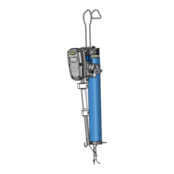
5450 Tie Stall
Operation, Service, and
Maintenance Instructions
BouMatic P.O. Box 8050 Madison, WI, 53708-8050 USA • Telephone: (608) 222-3484 Fax: (608) 222-9314 • www.boumatic.com
Remicourt 31, Rue Jules Melotte B 4350 Remicourt Belgium • Telephone: +32 (0)19 544 266 Fax: +32 (0)19 545 544
9e1026a
Advertisement
Table of Contents

Subscribe to Our Youtube Channel
Related Manuals for Boumatic 5450

Summary of Contents for Boumatic 5450
- Page 1 Operation, Service, and Maintenance Instructions BouMatic P.O. Box 8050 Madison, WI, 53708-8050 USA • Telephone: (608) 222-3484 Fax: (608) 222-9314 • www.boumatic.com Remicourt 31, Rue Jules Melotte B 4350 Remicourt Belgium • Telephone: +32 (0)19 544 266 Fax: +32 (0)19 545 544...
- Page 2 Under no circumstances These instructions aim to aid those responsible (outlined under “Re- will BouMatic be responsible for any problems caused in whole or sponsibilities”) for installing, operating, maintaining, troubleshooting, in part by any deviation from the procedures specified in these and servicing this product.
-
Page 3: Table Of Contents
2.1 Reviewing Personal Safety Messages .............. 4 3. Overview and Functions ................... 5 3.1 AMI 5450 Overview ..................5 3.1.1 Front View of AMI 5450 ..............5 3.1.3 LCD display ................... 6 3.1.4 LED Status Indicators ..............7 3.2 AMI 5450 Specifications ................8 3.3 Class II Wiring Recommendations .............. -
Page 4: Introduction
1. Introduction The BouMatic Advanced Milking Interface (AMI) 5450 The AMI 5450 is able to record the milk yield but milk yield indicator system will provide milk yield of does not meet DHIA or ICAR milk meter accuracies. the individual cows. -
Page 5: Overview And Functions
The LED Status Indicators will display the • The Numeric keys (1-9 and 0) are used to color for the mode that the AMI 5450 is in; enter a numeric value. If a Function key see Tables 1 and 2 for colors used during has not been selected, pressing "0"... -
Page 6: Lcd Display
See Figure 2. 3.1.2 LCD display The LCD displays all the relevant information for the current mode and state of the AMI 5450. The Active milking screen Figure 3 displays the following: Stall Number • This shows the stall number that was assigned to the AMI 5450 during instal- lation. -
Page 7: Led Status Indicators
3.1.3 LED Status Indicators See Table 1: LED Status Indicator, Color Patterns. Table 1. LED Status Indicator, Color Patterns Color Function Solid Flashing New Cow Assignment On - 0.8 second Off - 0.2 second Green Attached On Continuously Automatic mode. Milk Flow Established Attached Flashes at 1 Hertz... -
Page 8: Ami 5450 Specifications
3.2 AMI 5450 Specifications Pulsation, Front and Rear 600 milliamps operating Input Power current Voltage +24 VDC, regulated, 21.5 - 26.5 volts Short circuit (DC power supply adjusted to 25.5 volts) protection Current 200 milliamps typical, 225 milliamps Connector 1 piece... - Page 9 The example shown is for a barn with 16 5450TS milking systems and four power supplies. L1026_01 Tie Stall Operation, Service and Maintenance 9e1026a...
-
Page 10: Wire Gauge Vs. Wire Length Recommendations
8 and 10 ga. Wire sizes will need to be spliced with smaller ga. wires at the pow-er supply to fit into the power supply terminals. 3.5 Power Supply Recommendations: Number of 5450 Number of 4 Amp TS Detachers Power Supplies Connector handle - Insert the Recommended airline tube into the pulsation hose. -
Page 11: Mounting The Connector Valve Assembly
3.7 Mounting the Connector 7. At each punch location, drill a 37/64” (14.5 mm) diameter hole, then tap it to 3/8” NPT Valve Assembly thread. Be careful not to insert the tap over one half of its length. An oversized hole may The Connector milk line valve assembly mounts to cause a loose fit. - Page 12 Milk valve Plug old stallcock hole Milkline Stallcock 5/8” (16mm) Hose Threaded Nipple Pulsator airline L963_03 Black (2) Common or DC GND Black (1) + 24 VDX Ferrule Terminal Block Loop wires, do not cut Power Supply (+) +24 VDC Power Supply (-) Common or DC GND L963_04...
-
Page 13: Reviewing Installation Specifications
3.8 Reviewing Installation • For many stanchion barn installations, the 1/4” cable should be about 48” (1220mm) Specifications away from back of the cow platform. The Advantage TS should be positioned properly Plan the installation according to these guidelines: with respect to the udder in order to provide good retract motion. -
Page 14: Function Key Commands
The "A" Action menu is disabled for the 5450 Tie Stall version. Not all actions will be available depending on what mode the AMI 5450 is in. See section 3.5 for a full description of each action. See section 3.4 about Keypad and Display Functions. -
Page 15: Change The Language Display
3.10.3 Change the Language Display There are several languages available for the text display. To change the language used, scroll through the Function keys to select the [Chg Lang] (F1) Func- tion key. 1. Bring up the function menu by pressing the (F4) key. -
Page 16: Enter Or Change Cow Number
Pressing the Function key attached. will only activate the cylinder on the stall where the AMI 5450 is located. See Figure 13. Procedure when the milking unit is not attached: 1. Press the zero (0) on the numeric keypad. -
Page 17: Special Functions
3.11 Special Functions 3.11.2 Wash, End All AMI 5450s connected to prism above the wash 3.11.1 Wash, Start area can be put into the Milk mode by selecting End Wash [End Wash]. All AMI 5450s connected to Prism above the wash area can be placed into the Wash mode by selecting [Strt Note: End Wash and Start Milk will do exactly the Wash] from the (B) action menu. -
Page 18: New Cow
3.12 Recall Cow Data - Available Only If a Cow Number is Assigned When the AMI 5450 is not connected to a SmartDairy Controller the AMI will record the last 60 milkings. This information will allow the user to recall: produc-... -
Page 19: Diagnostic Functions
5450 Tie Stall or for downloading data. The communication test can be started at any AMI 5450 on the network that is not in Wash mode. If all the wiring is correct the communication test will Stop Communication Test L1015_29 flash the LED status indicator green on the AMI 5450. -
Page 20: Features
The milking and pulsation parameters are set to give over 14 MIPS (Million Instructions Per Second) to the AMI 5450 the capability of milking cows. When give fast and accurate control of all the milking func- the parlor type is selected during the configuration the tions. - Page 21 Maximum Milking Time: The Maximum Milking Manual Milk Time: The Manual Milk Time can be set Time can be set to remove the milking unit regard- to limit the amount of time that a detacher can stay less of milk flow if Manual mode is selected. When in Manual mode when milk flow is detected.
- Page 22 Extended Cylinder Retracted Open Shutoff Closed Pulsation Milk Flow T0 = detached position and ready to milk a cow T1 = Attach button pressed or milking unit is raised if using QuickStart T1 to T2 = Vacuum On Delay T1 to T3 = Pulsation Start Delay T1 to T4 = Let Down Delay T5 = milk flow is below Takeoff Flow Rate T6 to T7 = Retract Delay...
-
Page 23: Pulsation
4.5 Pulsation Pulsation can only be used with BouMatic pulsators for parlors that require individual stall pulsation. See Table 5. Pulsation Rate: The Pulsation Rate is the number of times the pulsators will turn on and off per minute. Front Ratio On Time: The Front Ratio On Time is set with the configuration software. -
Page 24: Operation
5.1 Understanding Basic Parts 5.1.1 Operation The Advanced Milking Interface Milk Yield Indicator The Advanced Milking Interface 5450 sensor (AMI) sensor (AMI MYI sensor) operation begins in the milk consists of three functional parts: Conductivity probes, hose before the milk even enters the sensor. The dip in Temperature sensor, and the sensor housing. -
Page 25: Electronic Control
Automatic Takeoff mode, the LED status indi- cators will be green. When the AMI 5450 is set to the Manual Takeoff mode the LED status indicators will During the delay period, whenever a high enough flow be orange. -
Page 26: Automatic Mode-Early Detach, At End Of Let-Down Delay
The LED status indicators on extended period of time, set the milking mode to the AMI 5450 will flash green constantly for the du- automatic. At this point the milking unit should stay ration of the delay period or until the level sensing attached and detach normally. -
Page 27: Using The Milking System
When the milk line, claw, etc. are being washed the ex- hand. The detacher will release the claw ternal surface of the AMI 5450 control can be washed and open the vacuum shutoff to the claw using a sponge or soft cloth. -
Page 28: Troubleshooting
6. Troubleshooting Table 4. Troubleshooting Guide Symptom Possible Cause Action Detacher does not Detacher and/or power supply not getting 24 VDC Check the voltage at the stallcock. power up. power. Check the voltage at the power supply output. Check the voltage at the power supply input. Check fuses or circuit breakers in AC power panel. -
Page 29: Maintenance
Table 4. Troubleshooting Guide Symptom Possible Cause Action Vacuum to the claw The detacher is not getting vacuum from the Verify that there is vacuum at the stallcock. does not shut off. stallcock. Check for a plugged vacuum hose. Vacuum shutoff solenoid is not turning on. Verify that the vacuum shutoff solenoid LED on the circuit board is turning on after pressing the Detach key. - Page 30 If parts become accidentally exposed, thoroughly wash them immediately and at the end of milking. Also, use of cleaners other than those recommended by BouMatic and excessive concentrations of those recommended is not advised. Use of nonrecommended chemicals will be done at the owner’s risk, and damages to the plastic parts...
Need help?
Do you have a question about the 5450 and is the answer not in the manual?
Questions and answers