
Related Manuals for Target Made By Design Horizontal Bookcase


Summary of Contents for Target Made By Design Horizontal Bookcase
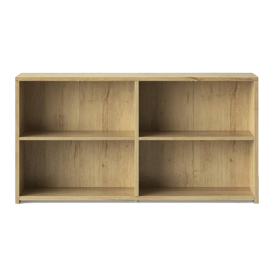
- Page 1 Made By Design™ Horizontal Bookcase - Espresso dpci 249-05-566 Horizontal Bookcase - Natural dpci 249-05-567 >> assembly instructions 4V – PJS_B_01...
-
Page 2: Before You Begin
2. Use the carton as a working surface to prevent product damage during assembly. 3. Gather all tools prior to assembly. tools needed Manufactured by Friul Intagli Industries spa, via Oderzo 68, 33080 Villanova di Prata, Italy Imported and distributed by Target Corporation, 1000 Nicollet Mall, Minneapolis, MN 55403, USA Guest Services: 1-800-440-0680... - Page 3 WARNING this product is intended for floor use only and not for wall mount use. Serious or fatal crushing injuries can occur from furniture tip-over. To help prevent tip over: • Install tip-over restraint provided • Place heaviest items on the lowest surfaces as far back from the front edge as possible. •...
- Page 4 table of contents introduction hardware parts list how to use the cam lock system assembly 8-25 QUESTIONS? Just call 855-MYTGTHOME (1-800-440-0680) for parts and service. For faster service, have the DPCI number ready when calling.
- Page 5 hardware (H1) x 10 (H2) x 10 (H3) x 12 (H5) x 8 (H6) x 2 (H4) x 8 support foot large cam metal dowel wooden dowel wedgefix housing wedgefix dowel (H12) x 3 (H7) x 4 (H8) x 40 (H9) x 1 (H10) x 1 (H11) x 3...
- Page 6 ITEM DESCRIPTION QUANTITY top panel bottom panel right end panel left end panel back panels shelves division panel D x1 C x1 E x2 Left side Right side (29 x 74.9cm) (72.2 x 72.3cm) (29 x 74.9cm) (29 x 182.9cm) (72.2 x 180.3cm) A x1 G x1...
- Page 7 how to use the cam lock system 180°...
- Page 8 step 1. (H1) x 4 (H3) x 4 large cam wooden dowel 1. Carefully tap small wooden dowels (H3) into place. 2. Refer to page 6 for instructions on how to use the cam lock system.
- Page 9 step 2. (H2) x 4 metal dowel 1. Attach 4x metal dowels (H2) into the pre-drilled holes on side panels, screw-In cam bolts must be screwed down flush.
- Page 10 step 3. (H1) x 2 (H3) x 4 large cam wooden dowel 1. Carefully tap small wooden dowels (H3) into place. 2. Refer to page 6 for instructions on how to use the cam lock system.
- Page 11 step 4. (H1) x 4 (H3) x 4 large cam wooden dowel 1. Carefully tap small wooden dowels (H3) into place. 2. Refer to page 6 for instructions on how to use the cam lock system.
- Page 12 step 5. (H2) x 6 metal dowel 1. Attach 6x metal dowels (H2) into the pre-drilled holes on top panel (A), screw-In cam bolts must be screwed down flush.
- Page 13 step 6. 180° 1. Attach bottom panel (B) onto side panels (C) and (D) as shown. Ensure metal dowels and wooden dowels are aligned correctly with the holes of matching parts before attaching. 2. Secure bottom panel (B) onto side panels (C) and (D) using screwdriver to turn fitting clockwise to fix. 3.
- Page 14 step 7. (H13) x 2 (H10) x 1 allen key conformat screw 1. Attach division panel (G) onto bottom panel (B) as show. 2. Secure division panel (G) using conformat screw (H13) and allen key (H10).
- Page 15 step 8. 180° 1. Attach top panel (A) onto side panels (C) (D) and division panel (G) as shown. Ensure metal dowels and wooden dowels are aligned correctly with the holes of matching parts before attaching. 2. Secure top panel (A) onto side panels (C) (D) and division panel (G) using screwdriver to turn fitting clockwise to fix. 3.
- Page 16 step 9. 1. Position back panels (E) as shown.
- Page 17 step 10. Y = J Y = J Import The ca be ‘squ back is 1. Before attaching the back panels (E), checking the correct allocation.
- Page 18 step 11. (H8) x 40 (H9) x 1 nail nail guide (H11) x 3 (H12) x 3 staple 63/64” flat-head screw 1. Attach back panels (E) onto back side of the unit using 40x nails (H8), with the help of the nail guide (H9), and 3x staples (H11) with 3x screws (H12).
- Page 19 step 12. (H7) x 4 (H6) x 2 support foot support foot 1. Push in by hand 4x support foot (H7) on side panels as shown. 2. Push in by hand 2x support foot (H6) on bottom panel (B) as shown.
- Page 20 step 13. 1. With help of an assistant carefully stand up the unit.
- Page 21 step 14. (H4) x 8 wedgefix housing 1. Push in by hand 4x wedgefix housing (H4) into the pre-drilled holes on shelves (F) as shown be carefully to the right alignment.
- Page 22 step 15. (H5) x 8 wedgefix dowel 1. Insert wedgefix dowels (H5) as shown. 2. Position the shelves (F) on the wedgefix dowels (H5) as shown. 3. Press firmily untill you don’t see the wedgefix dowels (H5).
- Page 23 step 16. For safest use of product all units should be secured to the wall with anti-tip hardware. If units are stacked or joined, it is required that units be secured to the wall with anti-tip hardware. (H14) x 2 (H18) x 2 L-bracket 3/8”...
- Page 24 step 17. (H16) x 1 plastic wall plug Wood. Masonry or brick. Cavity wall. If fixing to wood Drill 5/16 inch diameter Drill 5/16 inch diameter Wood. Masonry or brick. Cavity wall. make sure that it pilot hole and 3/4 inch deep pilot hole at the height If fixing to wood Drill 5/16 inch diameter...
- Page 25 step 18. For safest use of product all units should be secured to the wall with anti-tip hardware. If units are stacked or joined, it is required that units be secured to the wall with anti-tip hardware. (H15) x 2 (H17) x 2 spacer 2”3/8 screw TC...
- Page 26 QUESTIONS? Just call 855-MYTGTHOME (1-800-440-0680) for parts and service. For faster service, have the DPCI number ready when calling.
- Page 28 © 2018 Target. The Bullseye Design is a trademark of Target Brands, Inc. All rights reserved.
Need help?
Do you have a question about the Made By Design Horizontal Bookcase and is the answer not in the manual?
Questions and answers