Advertisement
Quick Links
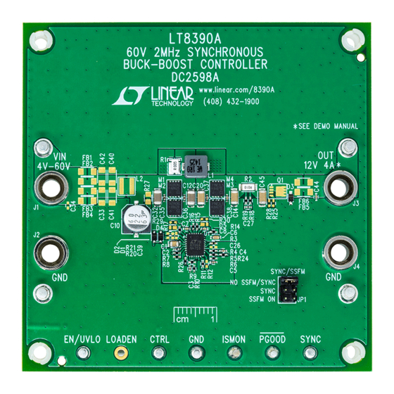
DESCRIPTION
Demonstration circuit 2598A is a 60V 2MHz synchronous
buck-boost controller featuring the
an input voltage from 4V to 24V (with transient to 60V) and
regulates 12V output at up to 4A. DC2598A features high
efficiency and 2MHz switching frequency, a high speed
for a 4-switch buck-boost controller. It has a PGOOD flag,
short-circuit fault protection, ISMON current-monitoring
output signal, and spread spectrum frequency modulation
(SSFM) or frequency synchronization.
The LT8390A has a wide input voltage range from 4V to
60V. It can regulate an output as a boost, a buck, or a
4-switch boost-buck controller. It has adjustable switch-
ing frequency between 600kHz and 2MHz. It has an option
for external frequency synchronization or spread spec-
trum frequency modulation. Its high switching frequency
is unique to buck-boost controller ICs. Because of this, it
can be used for high power when the input may be above,
below, or equal to the output.
DC2598A features an option to turn on spread spectrum
by simply changing the position of a jumper from "NO
SSFM/SYNC" to "SSFM" (or to "SYNC").
PERFORMANCE SUMMARY
PARAMETER
Input Voltage Range
Full Load (4A) Input Voltage Range
Typical Efficiency
Switching Frequency
Peak Switch Current Limit
(AC) Output Ripple
Input Under Voltage Lockout (Falling Turn-Off)
Input Under Voltage Lockout (Rising Turn-On)
V
ISMON
Maximum Load Current
Arrow.com.
Downloaded from
Small ceramic input and output capacitors are used to
LT
8390A. It accepts
save space and cost. There is a protection diode from
®
LED+ to GND to prevent negative ringing during a short-
circuit with long wires. Optional EMI input, output, and
gate resistor component placeholders exist when a low
EMI application is needed.
Under voltage lockout can be adjusted with a few resistors
and output voltage can be changed from 12V with FB resis-
tors changes. Please note that higher voltage outputs may
require higher voltage MOSFETs and output capacitors.
The LT8390A data sheet gives a complete description of the
part, operation and applications information. The data sheet
must be read in conjunction with this demo manual for
demonstration circuit 2598A. The LT8390AEUFD is assem-
bled in a 28-lead 4mm × 5mm plastic QFN package with a
thermally enhanced ground pad. LT8390A is also available
in a 28-Lead plastic TSSOP (FE) package. Proper board
layout is essential for maximum thermal performance. See
the data sheet section "Layout Considerations".
Design files for this circuit board are available at
http://www.linear.com/demo/DC2598A
L, LT, LTC, LTM, Linear Technology and the Linear logo are registered trademarks of Analog
Devices, Inc. All other trademarks are the property of their respective owners.
Specifications are at T
CONDITION
Operating
Component Temp Rise <60°C with No Airflow
12V Input, 12V 4A Output, 2MHz
R3 = 59.0k
R1 = 0.005Ω
12V Input, 12V 4A Output
R7 = 383k, R8 = 165k
R7 = 383k, R8 = 165k
12V 4A Output
12V Input, 12V Output
DEMO MANUAL DC2598A
60V 2MHz Synchronous
Buck-Boost Controller
= 25°C
A
MIN
4V
7V
4
LT8390A
TYP
MAX
60V
23V
90%
2MHz
10A
70mV
P-P
4.0V
5.0V
1.0V
4.5A
dc2598af
1
Advertisement

Related Manuals for Linear Technology LT8390A


Summary of Contents for Linear Technology LT8390A
- Page 1 Design files for this circuit board are available at SSFM/SYNC” to “SSFM” (or to ”SYNC”). http://www.linear.com/demo/DC2598A L, LT, LTC, LTM, Linear Technology and the Linear logo are registered trademarks of Analog Devices, Inc. All other trademarks are the property of their respective owners. PERFORMANCE SUMMARY Specifications are at T = 25°C...
-
Page 2: Quick Start Procedure
QUICK START PROCEDURE Demonstration circuit 2598A is easy to set up to evaluate the jumper in the SYNC position if an external SYNC the performance of the LT8390A Follow the procedure frequency source is connected to the SYNC pin. below: 4. - Page 3 DEMO MANUAL DC2598A QUICK START PROCEDURE LOAD CURRENT (A) dc2598a F02 Figure 2. DC2598A, LT8390A 2MHz Buck-Boost Efficiency 12V dc2598a F03 Figure 3. Recommended Maximum DC Current with No Airflow (for DC2598A) dc2598af Arrow.com. Arrow.com. Arrow.com. Downloaded from Downloaded from Downloaded from...
- Page 4 367.03 kHz 336.46 kHz Magnitude -0.000 dB -20.562 dB -20.562 dB Phase 75.120 deg 0.871 deg -74.249 deg Figure 5. DC2598A, LT8390A Bode Plot 12V Input, 12V 4A Output dc2598af Arrow.com. Arrow.com. Arrow.com. Arrow.com. Downloaded from Downloaded from Downloaded from Downloaded from...
-
Page 5: Parts List
DEMO MANUAL DC2598A PARTS LIST ITEM REFERENCE PART DESCRIPTION MANUFACTURER/PART NUMBER Required Circuit Components CAP ., 1μF, X7S, 100V, 10%, 0805 CAP ., 4.7μF, X5R, 10V, 10%, 0402 TDK, C1005X5R1A475K050BC CAP ., 0.47μF, X5R, 16V, 10%, 0402 TAIYO YUDEN, EMK105ABJ474KV-F CAP ., 2200pF, X7R, 25V,1 0%, 0402 MURATA, GRM155R71E222KA01D CAP ., 0.022μF, X7R, 25V, 10%, 0402... - Page 6 DEMO MANUAL DC2598A PARTS LIST ITEM REFERENCE PART DESCRIPTION MANUFACTURER/PART NUMBER RES., 124k, 1%, 1/16W, 0402 VISHAY, CRCW0402124KFKED RES., 75k, 1%, 1/16W, 0402 VISHAY, CRCW040275K0FKED R12, R20, R21, R25, R28, RES., OPTION, 0402 R29, R30 R14, R15, R16, R17, R24, R26 RES., 0Ω, 1/16W, 0402, AEC-Q200 VISHAY, CRCW04020000Z0ED R18, R19...
-
Page 7: Schematic Diagram
Information furnished by Linear Technology Corporation is believed to be accurate and reliable. However, no responsibility is assumed for its use. Linear Technology Corporation makes no representa- tion that the interconnection of its circuits as described herein will not infringe on existing patent rights. - Page 8 Linear Technology Corporation (LTC) provides the enclosed product(s) under the following AS IS conditions: This demonstration board (DEMO BOARD) kit being sold or provided by Linear Technology is intended for use for ENGINEERING DEVELOPMENT OR EVALUATION PURPOSES ONLY and is not provided by LTC for commercial use. As such, the DEMO BOARD herein may not be complete in terms of required design-, marketing-, and/or manufacturing-related protective considerations, including but not limited to product safety measures typically found in finished commercial goods.
Need help?
Do you have a question about the LT8390A and is the answer not in the manual?
Questions and answers