Advertisement
Description
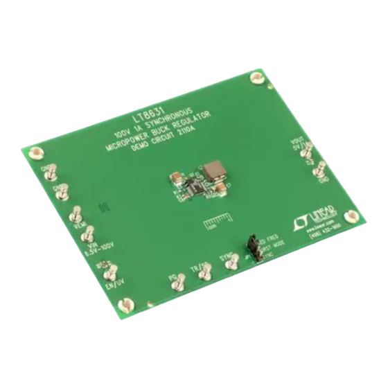
Demonstration circuit 2110A is a monolithic step-down
converter featuring
LT
8631. The demo board is designed
®
for 5V output from a 6.5V to 100V input at 400kHz switch-
ing frequency. The wide input range makes it suitable for
regulating power from a wide variety of sources, includ-
ing automotive, industrial systems and telecom supplies.
The LT8631 is a compact, high efficiency synchronous
monolithic step-down switching regulator. The power
switch, compensation and other necessary circuits are
inside of the LT8631 to minimize external components
and simplify design.
The LT8631 switching frequency can be programmed
either via oscillator resistor or external clock over a
100kHz to 1MHz range. The SYNC pin on the demo board
is grounded (JP1 at Burst Mode
low ripple Burst Mode operation. To synchronize to an
external clock, move JP1 to SYNC and apply the external
clock to the SYNC turret. If the pulse-skipping operation
is required, move JP1 to fixed frequency position. Figure 1
shows the efficiency of the circuit at 12V input at the Burst
Mode selection.
The demo board has an EMI filter installed. The EMI per-
formance of the board (with EMI filter) is shown in Figure
2. The red line in Figure 2 is CISPR25 Class 5 peak limit.
The figure shows that the circuit passes the test with a
wide margin. To achieve EMI/EMC performance as shown
performance summary
SYMBOL
PARAMETER
V
Input Supply Range
IN
V
Output Voltage
OUT
f
Switching Frequency
SW
I
Max Output Current
OUT
E
Efficiency at DC
FE
Micropower Step-Down Regulator
position) by default for
®
Specifications are at T
CONDITIONS
R
= 25.5kΩ
T
V
= 12V
IN
V
= 12V, I
IN
V
= 12V, I
IN
DEMO MANUAL DC2110A
100V, 1A Synchronous
95
90
85
80
75
70
65
60
55
50
0
0.1 0.2
0.3
Figure 1. LT8631 Efficiency vs Load Current
in Figure 2, the input EMI filter is required and the input
voltage should be applied at V
The LT8631 data sheet gives a complete description of
the part, operation and application information. The data
sheet must be read in conjunction with this demo manual
for demo circuit 2110A. The LT8631 is assembled in a
20-lead TSSOP packages. Proper board layout is essential
for maximum thermal and electrical performance. See the
data sheet sections for details.
Design files for this circuit board are available at
http://www.linear.com/demo/DC2110A
L, LT, LTC, LTM, Linear Technology, Burst Mode and the Linear logo are registered trademarks
of Linear Technology Corporation. All other trademarks are the property of their respective
owners.
= 25°C
A
= 1A
OUT
= 0.4A
OUT
LT8631
f
= 400kHz
SW
V
= 12V
IN
V
= 5V
OUT
0.4
0.5
0.6
0.7
0.8
0.9
1
LOAD CURRENT (A)
DC2110a F01
turret pin, not V
EMI
MIN
TYP
MAX
6.5
100
4.88
5.04
5.2
370
400
430
1
82.6
89.5
.
IN
UNITS
V
V
kHz
A
%
%
dc2110af
1
Advertisement
Table of Contents

Related Manuals for Linear Technology DC2110A


Summary of Contents for Linear Technology DC2110A
- Page 1 The figure shows that the circuit passes the test with a wide margin. To achieve EMI/EMC performance as shown L, LT, LTC, LTM, Linear Technology, Burst Mode and the Linear logo are registered trademarks of Linear Technology Corporation. All other trademarks are the property of their respective owners.
- Page 2 Class 5 Peak 1000 Frequency (MHz) Detector: +Peak Polarity: Horizontal Data Class 5 Peak 1000 Frequency (MHz) Figure 2. LT8631 Demo Circuit DC2110A EMI Performance in CISPR25 Radiated Emission Test (14V Input from V Turret Pin, I = 1A) dc2110af...
- Page 3 DEMO MANUAL DC2110A Quick start proceDure – – – POWER SUPPLY – LOAD – – Figure 3. Proper Measurement Equipment Setup Figure 4. Measurement Input or Output Ripple dc2110af...
- Page 4 DEMO MANUAL DC2110A parts List ITEM REFERENCE PART DESCRIPTION MANUFACTURER/PART NUMBER Required Circuit Components CAP, 0.1µF, X7R, 10V, 10% 0402 TDK, C1005X7R1A104K CAP, 2.2µF, X5R, 10V, 10% 0402 TDK, C1005X5R1A225K050BC CAP, 4.7pF, C0G, 50V, 0.25pF 0603 MURATA, GRM1885C1H4R7CA01D CAP, 47µF, X7R, 10V, 20% 1210 MURATA, GRM32ER71A476KE15L CAP, 0.1µF, X7R, 10V, 10% 0603...
- Page 5 Information furnished by Linear Technology Corporation is believed to be accurate and reliable. However, no responsibility is assumed for its use. Linear Technology Corporation makes no representa- tion that the interconnection of its circuits as described herein will not infringe on existing patent rights.
- Page 6 Linear Technology Corporation (LTC) provides the enclosed product(s) under the following AS IS conditions: This demonstration board (DEMO BOARD) kit being sold or provided by Linear Technology is intended for use for ENGINEERING DEVELOPMENT OR EVALUATION PURPOSES ONLY and is not provided by LTC for commercial use. As such, the DEMO BOARD herein may not be complete in terms of required design-, marketing-, and/or manufacturing-related protective considerations, including but not limited to product safety measures typically found in finished commercial goods.
- Page 7 X-ON Electronics Largest Supplier of Electrical and Electronic Components Click to view similar products for category: Power Management IC Development Tools Click to view products by manufacturer: Analog Devices Other Similar products are found below : EVAL-ADM1168LQEBZ EVB-EP5348UI MIC23451-AAAYFL EV MIC5281YMME EV DA9063-EVAL ADP122-3.3-EVALZ ADP130- 0.8-EVALZ ADP130-1.2-EVALZ ADP130-1.5-EVALZ ADP130-1.8-EVALZ ADP1714-3.3-EVALZ ADP1716-2.5-EVALZ ADP1740-1.5- EVALZ ADP1752-1.5-EVALZ ADP1828LC-EVALZ ADP1870-0.3-EVALZ ADP1871-0.6-EVALZ ADP1873-0.6-EVALZ ADP1874-0.3- EVALZ ADP1882-1.0-EVALZ ADP199CB-EVALZ ADP2102-1.25-EVALZ ADP2102-1.875EVALZ ADP2102-1.8-EVALZ ADP2102-2-...
Need help?
Do you have a question about the DC2110A and is the answer not in the manual?
Questions and answers