Advertisement
DESCRIPTION
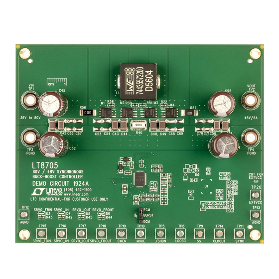
Demonstration circuit 1924A is a high performance buck-
boost converter featuring the
from input voltages above, below or equal to the output
voltage. The demo board input range is 36V to 80V. The
output is optimized for 48V at 5A, with the output current
limit set at 7A. (The circuit will operate with lower input
voltage than 36V if load current is reduced).
The controller has integrated input current, input voltage,
output current and output voltage regulators. The one
regulator that wants to decrease current gets control over
the compensation pin VC. The inductor current is controlled
by the VC signal that is fed into a current comparator
together with a ramp compensation signal.
While the current mode control limits the inductor current
both in normal and in reverse direction, these current
limits have some variation as input voltage changes. The
input and output current regulators offer more accurate
current limits.
The input voltage regulator is typically used in applica-
tions with solar panels or other high impedance power
sources, and will reduce the current if the input voltage
drops below the set point.
The operating mode of the controller is determined
through the MODE pin (jumper JP1) and can be set to
discontinuous mode, forced continuous mode and Burst
Mode
operation.
®
The LT8705 is capable of bidirectional operation when
operating in forced continuous mode. Additional circuitry
may be needed depending on the application.
Arrow.com.
Downloaded from
80V V
LT
8705
that can operate
®
DEMO MANUAL DC1924A
and V
IN
OUT
4-Switch Buck-Boost DC/DC
The CLKOUT output and the SYNC input can be used
to synchronize two DC1924A circuits with 180 degree
phase shift.
By feeding the LT8705 from a separate low voltage sup-
ply, the power dissipation can be reduced. To supply the
LT8705 chip from an external voltage supply (> 6.4V), cut
the trace as marked on the board to disconnect the EXTVCC
pin from V
. The LT8705 will start when voltage is ap-
OUT
plied at the input (VIN pin), and when it is running it will
draw current from the EXTVCC pin if the voltage is > 6.4V.
Typical efficiency with 5A load is above 97% across a 36V
to 72V input range using the supplied inductor. Lower
core loss can be achieved by using a ferrite core inductor.
The LT8705 data sheet gives a complete description of
the part, operation and application information. The data
sheet should be read in conjunction with this quick start
guide for demo circuit 1924A. The input voltage range of
the LT8705 itself is 2.8V (need EXTVCC > 6.4V) to 80V
and the output range is 1.3V to 80V.
The LT8705EUHF is assembled in a 38-Lead (5mm ×
7mm) plastic QFN package with a thermal pad underneath
the chip. Proper board layout is essential for maximum
thermal and electrical performance. See the data sheet
section Circuit Board Layout Checklist.
Design files for this circuit board are available at
http://www.linear.com/demo/DC1924A
L, LT, LTC, LTM, Linear Technology Burst Mode and the Linear logo are registered trademarks
of Linear Technology Corporation. All other trademarks are the property of their respective
owners.
LT8705
Synchronous
Controller
dc1924afa
1
Advertisement
Table of Contents

Related Manuals for Linear Technology LT8705


Summary of Contents for Linear Technology LT8705
- Page 1 The LT8705 is capable of bidirectional operation when L, LT, LTC, LTM, Linear Technology Burst Mode and the Linear logo are registered trademarks operating in forced continuous mode. Additional circuitry of Linear Technology Corporation. All other trademarks are the property of their respective owners.
-
Page 2: Performance Summary
DEMO MANUAL DC1924A PERFORMANCE SUMMARY Specifications are at T = 25°C SYMBOL PARAMETER CONDITIONS UNITS Input Supply Range Note: Output Power Is Limited When V < 30V Output Voltage Maximum Load Current Output Current Limit Switching Frequency Efficiency at DC Input = 36V, V = 48V, I = 5A... -
Page 3: Quick Start Procedure
1. Demonstration circuit 1924A is easy to set up to evalu- 7. Once the proper output voltage is established, adjust the ate the performance of the LT8705. Refer to Figure 2 load and the input voltage within the operating range... - Page 4 DEMO MANUAL DC1924A QUICK START PROCEDURE Figure 2. Test Setup dc1924afa Arrow.com. Arrow.com. Arrow.com. Arrow.com. Downloaded from Downloaded from Downloaded from Downloaded from...
-
Page 5: Parts List
VISHAY CRCW060324K3FKEA RES 56.2k 1/10W 1% 0603 SMD VISHAY CRCW060356K2FKEA RES 0.007Ω 1W 1% 2512 SMD VISHAY CRCW25127L000FEA RES 4.02Ω 1/10W 1% 0603 SMD VISHAY CRCW06034R02FKEA LT8705 SYNCHRONOUS 4 SWITCH BUCK-BOOST LINEAR TECH LT8705EUHF#PBF DC/DC CONTROLLER dc1924afa Arrow.com. Arrow.com. Arrow.com. - Page 6 DEMO MANUAL DC1924A PARTS LIST Additional Demo Board Circuit Components C12, C60 CAP 0603 OPTION CAP 0603 OPTION C53, C54, C66-C71 CAP 1812 OPTION CAP 1812 OPTION M1-1, M2-1, M3-1, M4-1 MOSFET POWER56 OPTION MOSFET POWER56 OPTION R53, R54, R59, R60 RES 0603 OPTION RES 0603 OPTION R22, R39, R48, R55...
-
Page 7: Schematic Diagram
Information furnished by Linear Technology Corporation is believed to be accurate and reliable. However, no responsibility is assumed for its use. Linear Technology Corporation makes no representa- tion that the interconnection of its circuits as described herein will not infringe on existing patent rights. - Page 8 Linear Technology Corporation (LTC) provides the enclosed product(s) under the following AS IS conditions: This demonstration board (DEMO BOARD) kit being sold or provided by Linear Technology is intended for use for ENGINEERING DEVELOPMENT OR EVALUATION PURPOSES ONLY and is not provided by LTC for commercial use. As such, the DEMO BOARD herein may not be complete in terms of required design-, marketing-, and/or manufacturing-related protective considerations, including but not limited to product safety measures typically found in finished commercial goods.
Need help?
Do you have a question about the LT8705 and is the answer not in the manual?
Questions and answers