Table of Contents
Advertisement
Quick Links
Advertisement
Table of Contents

Related Manuals for Lufft MARWIS


Summary of Contents for Lufft MARWIS
- Page 2 Operating Manual MARWIS-UMB / STARWIS-UMB English © G. Lufft Mess- und Regeltechnik GmbH, Fellbach, Germany. Subject to change without notice.
-
Page 3: Table Of Contents
4.6 Water film height..........................10 4.7 Road condition............................. 10 4.8 Ice percentage............................. 10 4.9 Snow Height............................10 4.10 Friction............................... 10 4.11 Sensor technology MARWIS-UMB / STARWIS-UMB.................11 4.12 Status-LED............................12 5 Generation of measurements ........................12 5.1 Current measurement (act)........................12 6 Operation modes............................13 6.1 Normal operation.......................... - Page 4 Operating Manual V 3.3 / 9 Dec 2019 MARWIS-UMB / STARWIS-UMB 8.4.1 Connecting the MARWIS-UMB / STARWIS-UMB to the protective housing........22 8.5 Example: Mounting with magnetic bar carrier for horizontal installation and short protective housing.27 8.6 Example: Mounting with magnetic bar carrier for vertical installation and long protective housing..28 8.7 Mounted correctly?..........................
- Page 5 20.3.5.1 CAN-ID..........................52 20.3.5.2 Transmission format......................53 20.3.6 Remote Query........................... 53 20.3.7 Configuration of a trigger......................53 20.3.7.1 CAN-ID..........................53 20.3.7.2 Trigger format........................54 20.3.8 Status and error codes....................... 55 20.3.9 Data types..........................56 Subject index..............................57 G. Lufft Mess-und Regeltechnik GmbH...
-
Page 6: Read Before Use
MARWIS-UMB Operating Manual V 3.3 / 9 Dec 2019 Read before use Please read this Operating Manual carefully and keep it handy for future reference. Please note that various components of the sensor and the described software may look somewhat different from those shown in the illustrations in this operating manual. -
Page 7: Brand Names
Part numbers 3.1 MARWIS-UMB 8900.U03....MARWIS-UMB for 1 m (3 ¼ ft) measuring distance to the ground 8900.U04....MARWIS-UMB for 2 m (6 ½ ft) measuring distance to the ground 8900.U05....MARWIS-UMB for 0.5 m (1 ¾ ft) measuring distance to the ground 8711.U55....STARWIS-UMB for 5.5 m (18 ft) measuring distance to the ground... -
Page 8: Accessories
Firmware......latest firmware for the equipment • MARWIS App for iOS operating systems can be downloaded from iTunes. The MARWIS-App for Android is available in Google Playstore. Communication has been tested at a maximum cable length of 15m (49 ¼ ft) with a bit rate of 115200 baud... -
Page 9: Equipment Description
In accordance with the demands on road traffic meteorological network sensors are mounted on vehicles. MARWIS-UMB for the detection of water, ice, snow and friction can be installed on vehicles. The distance between the sensor and the road must be either 0.5, 1 m or 2 m (1 ¾ ft , 3 ¼... -
Page 10: Water Film Height
Note: The grip of a road is determined basically by the texture of its surface. The friction value of the MARWIS-UMB / STARWIS-UMB indicates to which degree the maximum possible grip of a specific road is reached, respectively how much it has been reduced by ambient conditions. -
Page 11: Sensor Technology Marwis-Umb / Starwis-Umb
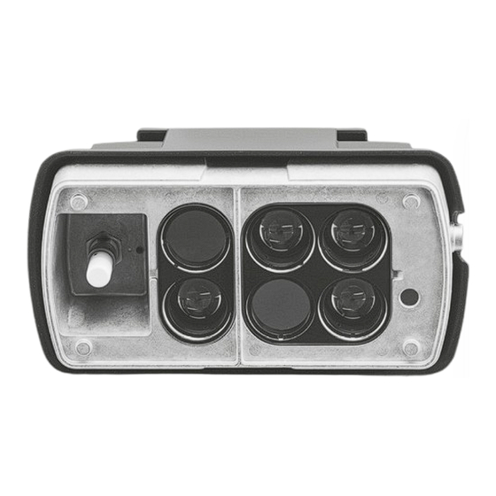
Operating Manual V 3.3 / 9 Dec 2019 MARWIS-UMB 4.11 Sensor technology MARWIS-UMB / STARWIS-UMB Illustration 2: MARWIS-UMB / STARWIS-UMB Components Abbildung 3: Lateral temperature sensor (only MARWIS-UMB) Chapter 4, Equipment description... -
Page 12: Status-Led
Operating Manual V 3.3 / 9 Dec 2019 4.12 Status-LED The device is equipped with a status LED which indicates the current state of the MARWIS-UMB / STARWIS-UMB. A blinking LED in any colour means that UMB data transfer is taking place through RS485 or Bluetooth. -
Page 13: Operation Modes
MARWIS-UMB Operation modes 6.1 Normal operation The MARWIS-UMB / STARWIS-UMB is switched on and off by connecting and disconnecting the power supply. After being switched on it takes a starting time of about 10 seconds before the first measure- ment values appear. Depending on the operating temperature and on the current ambient temperature a warm up phase of 5 up to 15 minutes may be required before the first plausible values appear. -
Page 14: Measurement Output
7.1.3 Relative Humidity Sampling rate..1 second Units......% Channels: Measuring range UMB Channel Measurement variable (float32) unit Relative humidity 7.1.4 Dew point temperature Sampling rate..1 second Units......ºC; ºF Channels: Measuring range UMB Channel Measurement variable (float32) unit MARWIS-UMB only Chapter 7, Measurement output... -
Page 15: Relative Humidity At Road Temperature
Operating Manual V 3.3 / 9 Dec 2019 MARWIS-UMB Dew point temperature -50.0 60.0 ºC Dew point temperature -58.0 140.0 ºF 7.1.5 Relative humidity at road temperature Sampling rate..1 second Units......% r.h. Channels: Measuring range UMB Channel Measurement variable (float32) -
Page 16: Ice Percentage
MARWIS-UMB Operating Manual V 3.3 / 9 Dec 2019 damp ice-covered Road condition snow-/ice-covered chemically wet water + ice snow-covered undefined dry: no liquid water on the road; water film height below damp threshold damp: liquid water on the road;... -
Page 17: Additional Sensor Information
Operating Manual V 3.3 / 9 Dec 2019 MARWIS-UMB Units......none Channels: Measuring range UMB Channel Measurement variable (float32) unit Friction none 7.2 Additional sensor information The sensor delivers more information about its state and functioning. 7.2.1 Device status UMB channel... - Page 18 MARWIS-UMB Operating Manual V 3.3 / 9 Dec 2019 Error at monitor measurement (LED defective) NIR measurement ok Bit 3 NIR measurement NIR measurement invalid Bit 4 – 7 RESERVED Adjustment profile valid Invalid adjustment Bit 8 Invalid adjustment profile selected; WFH measurement...
-
Page 19: Mounting
8.3 Mounting height The measuring distance of 1 m or 2 m (3¼ ft or 6½ ft) and 5.5 m (16 ⅜ ft) for the 2 MARWIS- UMB types and the STARWIS-UMB respectively refer to the distance from the sensor front (glass) to the road. -
Page 20: 8900.U05, Mounting With Short Protective Housing, Angle 20º
MARWIS-UMB Operating Manual V 3.3 / 9 Dec 2019 8.3.3 8900.U05, Mounting with short protective housing, angle 20º Minimal height..33 cm..(13 in)....measuring distance ..35 cm. .(13 ¾ in) Ideal height....47 cm. .(18 ½ in)....measuring distance ..50 cm. .(19 ¾ in) Maximum height..61 cm..(24 in)....measuring distance ..65 cm. - Page 21 Operating Manual V 3.3 / 9 Dec 2019 MARWIS-UMB Illustration 5: Mounting of STARWIS-UMB Chapter 8, Mounting...
-
Page 22: Protective Housing
Furthermore it is equipped with a flange which can be used for fixing it. 8.4.1 Connecting the MARWIS-UMB / STARWIS-UMB to the protective housing Loosen the screws on the upper side of the MARWIS-UMB / STARWIS-UMB and take off the plastic stripes. - Page 23 Operating Manual V 3.3 / 9 Dec 2019 MARWIS-UMB The delivery of the protective housing includes 2 clamp straps for fixing it to the MARWIS-UMB / STARWIS-UMB. Illustration 9: clamp strap Place the clamp straps that have come with the protective housing on the MARWIS-UMB / STARWIS-UMB so that the profiles of the two clamp straps fit in neatly with the dents on the upper side of the MARWIS-UMB / STARWIS-UMB.
- Page 24 MARWIS-UMB Operating Manual V 3.3 / 9 Dec 2019 Mount the plastic bars of the clamping device on the MARWIS-UMB / STARWIS-UMB; insert the screws and tighten them. Illustration 13: Insert screws Illustration 12: Fixing the clamp straps Illustration 14: Tighten screws...
- Page 25 Operating Manual V 3.3 / 9 Dec 2019 MARWIS-UMB Put the MARWIS-UMB / STARWIS-UMB on the protective housing so that the ends of the clamp straps come close to the hitch of the housing. Illustration 15: Hitch on protective housing...
- Page 26 Illustration 20: clamp straps latched Illustration 19: Protective housing connected Removing the MARWIS-UMB / STARWIS-UMB from the protective housing is easily done by again inserting a screw driver into the ears of the clamp straps. By pressing outwards downwards the connection can be opened.
-
Page 27: Example: Mounting With Magnetic Bar Carrier For Horizontal Installation And Short Protective Housing
Operating Manual V 3.3 / 9 Dec 2019 MARWIS-UMB 8.5 Example: Mounting with magnetic bar carrier for horizontal installation and short protective housing Illustration 21: Mounting on passenger car Illustration 22: Mounting on passenger car Chapter 8, Mounting... -
Page 28: Example: Mounting With Magnetic Bar Carrier For Vertical Installation And Long Protective Housing
8.6 Example: Mounting with magnetic bar carrier for vertical installation and long protective housing Illustration 23: Vertical mounting (door of a van) 8.7 Mounted correctly? Send us a photo of your MARWIS-UMB installation to myMARWIS@lufft.com. The MARWIS- UMB team will have a look and send you feedback. Chapter 8, Mounting... -
Page 29: Connections
MARWIS-UMB Connections The MARWIS-UMB housing is equipped with an 8-pole screw plug socket which serves for con- necting the supply voltage and the RS485 interface. The connection cable has to be ordered seperately in the desired length (5 or 15 meters / 49 ¼ ft or 16 ⅜ ft). -
Page 30: Supply Voltage
The device is equipped with a half duplex 2 wire RS484 interface for configuration, measure- ment retrieval and firmware update. The MARWIS-UMB sampling rate can be adjusted in steps of 0.1 s to values between once per 0.1 s and once every 5 seconds. The STARWIS-UMB sampling rate can be adjusted steps of 1 second to values between once per second and once every 60 seconds. -
Page 31: Commissioning
To this end, the MARWIS-UMB has to be installed on the measuring vehicle in the planned posi - tion. The adaption must take place on a dry piece of road and ist carried out on a stationary vehicle, i.e. -
Page 32: Illustration Of How The Road Condition Is Determined
The averaging time can be configured via the 'number of measurements for averaging'. The maximum number for averaging is 60 values. If this value is set for example to 10 and the default update rate is used, MARWIS-UMB averages over 10 100ms values, that is over 1 second. STARWIS-UMB averages over 10 1s values, that is over 10 seconds. -
Page 33: Important Hints Prior To Commissioning
In a vehicle with a stop-start system the cigarette lighter is usually left without power • supply during the starting process. If the MARWIS-UMB receives its power supply from the cigarette lighter in such a car, it will in this case carry out a reset which may lead to data gaps. -
Page 34: Carrying Out The Sensor Adaption
11 Carrying out the sensor adaption 11.1 Adaption with the MARWIS-App The adaption of the sensor can be carried out with the MARWIS-App on the iPad or Android tablet PC or with the program ConfigTool.Net on Windows PC. The exact proceeding is described in the manual / help of the respective app or program. -
Page 35: Firmware Update
If you use a chemical cleaning tissue, pay attention to the corresponding instructions. Note: By no means use a pressure washer for cleaning the MARWIS-UMB / STARWIS-UMB. Don't forget to take off your MARWIS-UMB before driving into a car wash. -
Page 36: Technical Data
MARWIS-UMB Operating Manual V 3.3 / 9 Dec 2019 15 Technical Data 15.1 Device Power supply: 10 – 28 V DC on the sensor Power input: ca. 3 VA without heating, 50 VA with heating Protection class: IP68 Measuring distance 8900.U0 3... -
Page 37: Measuring Range / Accuracy
15 Tests for checking the water film height can be carried out on even ground made from sleek not water absorbing material with a minimum reflectivity of 0.5 i.e. 50% of the energy is being reflected. With a distance of 1 -2 m to the MARWIS-UMB the test ground has to be at least 25 x 25 cm in size, with a distance of 5m (STARWIS-UMB) it must be 60 x 60 cm. -
Page 38: Relative Humidity
Resolution 0.01 mm 16 Only MARWIS-UMB 17 In a stable state, i.e. the definite value has been reached and the environment conditions are not subject to strong variations as e.g. when driving in a landscape with quick changes of wood and open space... -
Page 39: Drawings
Operating Manual V 3.3 / 9 Dec 2019 MARWIS-UMB 15.3 Drawings 15.3.1 MARWIS-UMB / STARWIS-UMB with short protective housing Illustration 28: MARWIS-UMB with short protective housing Chapter 15, Technical Data... -
Page 40: Marws-Umb With Long Protective Housing
MARWIS-UMB Operating Manual V 3.3 / 9 Dec 2019 Illustration 29: MARWIS-UMB with short protective housing 15.3.2 MARWS-UMB with long protective housing Illustration 30: Long protective housing – lateral view 19 The STARWIS-UMB can also be used with the long protective housing. Since this is probably a rare case it not explicitly mentioned herein. - Page 41 Operating Manual V 3.3 / 9 Dec 2019 MARWIS-UMB Illustration 31: Long protective housing – back view Chapter 15, Technical Data...
-
Page 42: Declaration Of Conformity
16.1 EC Certificate of Conformity Product: Mobile Road Sensor Type MARWIS-UMB (Order No. 8900.Uxx) STARWIS-UMB (Best.-Nr. 8711.U55) We herewith certify that the above mentioned equipment complies in design and construction with the below mentioned Directives of the European Union 2011/65/EU... -
Page 43: Ic Compliance Statement (Ca)
16.3 IC Compliance statement (CA) Product: Mobile Road Sensor Type MARWIS-UMB (Order No. 8900.Uxx) STARWIS-UMB (Best.-Nr. 8711.U55) This device contains equipment with the IC ID: 5325A-0946. This device complies with Industry Canada licence-exempt RSS standard(s). Operation is subject to the following two conditions:... -
Page 44: Disturbances
MARWIS-UMB Operating Manual V 3.3 / 9 Dec 2019 17 Disturbances 17.1 Possible errors occurring on the MARWIS-UMB / STARWIS-UMB Error descriptions Cause / remedy Device does not allow polling or does Check status-LED • not respond Check supply voltage •... -
Page 45: Disposal
Operating Manual V 3.3 / 9 Dec 2019 MARWIS-UMB Dirt on the MARWIS-UMB front glass pane, e.g. due to spume on wet roads ● Very dark road surface (new blacktop – MARWIS-UMB) ● Parked vehicle below the sensor (STARWIS-UMB) ●... -
Page 46: Appendix
MARWIS-UMB Operating Manual V 3.3 / 9 Dec 2019 20 Appendix 20.1 Channel List Summary The channel assignment described here applies to online data requests in UMB protocol UMB Channel Measuring Range Min Max avg Measurement Variable (float32) unit Road surface temperature Road surface temperature -40.0... -
Page 47: Communication In Binary Protocol
Only one example of an online data request is described in this operating manual. Please refer to the current version of the UMB protodol for all commands and the exact operation mode of the protocol (available for download at www.lufft.com) Chapter 20, Appendix... -
Page 48: Framing
MARWIS-UMB Operating Manual V 3.3 / 9 Dec 2019 Note: Communication with the sensor takes place in accordance with the master-slave principle, i.e. there must only be ONE requesting unit in a network. 20.2.1 Framing The data frame is constructed as follows: 11…... -
Page 49: Example For Creating Addresses
Operating Manual V 3.3 / 9 Dec 2019 MARWIS-UMB 20.2.3 Example for creating addresses If e.g. a MARWIS-UMB / STARWIS-UMB shall be addressed with Device ID 001 this works as follows: Class ID for MARWIS-UMB / STARWIS-UMB is 10d = Ah Device ID is e.g. -
Page 50: Example Online Data Query Multiple Channels
MARWIS-UMB Operating Manual V 3.3 / 9 Dec 2019 20.2.5 Example online data query multiple channels Recording of a binary request with “online data query multiple channels” (2Fh) for reading the current road surface temperature (channel 100) and road condition (channel 900) =... - Page 51 Operating Manual V 3.3 / 9 Dec 2019 MARWIS-UMB <value> requested value Example: Retrieval of 3 measurement values Channel 100 (0064h): Road temperature in °C Channel 600 (0258h): water film height in µm Channel 900 (0384h): Road condition 1st Request:...
-
Page 52: Can Protocol (Version 1.0)
20.3 CAN Protocol (Version 1.0) 20.3.1 General remarks All Marwis measuring channels can communicate over the CAN interface. Each value will be sent in its own CAN telegram. In order to transfer a measured value it is either possible to send a remote telegram which will cause the value to be transferred once or to configure a trigger so that the value is sent automatically time and time again. -
Page 53: Transmission Format
0x10 0x01 Road state: 1 (humid) 20.3.6 Remote Query Marwis supports remote value queries. Following the CAN specifications the CAN ID corresponds to the CAN ID which is used for transmitting the corresponding value with additionally set RTR bit. The required value is transferred instantly one time only. -
Page 54: Trigger Format
MARWIS-UMB Operating Manual V 3.3 / 9 Dec 2019 Examples: Value Value number 11 Bit 18 Bit RTR CAN-ID (dez. / hex) Identifier Identifier (extended) (hex) (hex) Road temperature in °C 0x001 0x00064 0x00040064 100d = 0x0064h Water film height in µm... -
Page 55: Status And Error Codes
Operating Manual V 3.3 / 9 Dec 2019 MARWIS-UMB Trigger type = 4: The triggers “miniumum” and “maximum” will have the corresponding value transferred only if it exceeds or falls below the specified limit value. The limit value has to be described in the same data format and with the same unit that are used for the transfer of the measured value. -
Page 56: Data Types
MARWIS-UMB Operating Manual V 3.3 / 9 Dec 2019 <status> Define Description VALUE_OVERFLOW 50h (80d) Measured value (+Offset) are out of the specified range. 51h (81d) VALUE_UNDERFLOW 52h (82d) CHANNEL_OVERRANGE Measured value (physically) is out of the measuring range (e.g. ADC overrange) -
Page 57: Subject Index
Operating Manual V 3.3 / 9 Dec 2019 MARWIS-UMB Subject index Subject index Mast.............8, 19f., 34, 45 Measuring distance......7, 19f., 31, 36 Adaption..........4, 31, 33f., 41 Mounting........3f., 8, 19f., 27f., 31 Addressing............4, 45 Mounting height..........3, 19 Angle............3, 19f., 31 MyMarwis..............28 App..............8, 30, 34... - Page 58 Operating Manual MARWIS-UMB / STARWIS-UMB English © G. Lufft Mess- und Regeltechnik GmbH, Fellbach, Germany. Subject to change without notice.
Need help?
Do you have a question about the MARWIS and is the answer not in the manual?
Questions and answers